Hi Hugh, I was not thinking of changing anything. I have my amps made and am happy with them.
Nico
I'm happy too with all the results, it is just that I want to explore more possibilities according to my current needs. Definitely I agree that simple solutions like a resistor on the spot is always more elegant and probably better sounding solution.
")
I guess it's just me the cat and my curiosity, hopefully not killing me.
Last edited:
Since Elektor's IGBT output amplifier from the 80's I've been expecting such a new approach to that technology. Yet not so simple (not so SSA=NSSSA!), this thread tells us that there is always something to be discovered, or to improve. Thank you all for the effort and invaluable teachings!
Regards,
Max.
You're welcome Max. Thanks.
Yes, always something to discover and improve ... work in progress to be continued.
Lasy cat and nico, in goal to drive speakers with "low" inpedance sink (not 1Ohms at all but more classical between 3 and 4) wouldn't it be an advantage to use double die lateral mosfet as Exicon ECF20N20/ECF20P20 or Magnatec BUZ900/BUZ905DP instesd of built in two parallel simple die. The advantage I see in is no matching between parallel devices and room feet gain. I have built several years ago a 2SK1058/2SJ162 (2 pair per rail) amp with +/-36V rail. It was able to drive in my domestical classical use a wide range of speaker sofar as a couple of bookshelf with a 4 ohms/87db scanspeak midwoofer. But what i am unable to do is to say what such an output stage need for modification in lasy cat simple lateral mosfet (one pair sk158//sj162) or in Nico triple pair output configuration => in few words : how to drive such a double die unit.
Marc
Marc
Idefix..
would opt for the more resilient BD140/139 pair for the drivers and increasing current to app 10-15 mA..
Instead of 2sa970/2sc2240 in Lasy cat simple configuration?
Marc
nope would go for Nico's version with the extra driver in the circuit. It has a 100 times lower distortion and a much better drive of the output..
Q-5;Q-6 to BD 140/139, change resistor R11/12 to app 140 ohm and use R13/trimmer to set the Current through the outputs.
Thanks for advices i locate modification, i will redrawn alex pec routing as Exicon present TO3 metal can. In same time will add more space to allow more possibility in chose of 10mf smoothing cap choice : 22,5mm is not a current size in europe
Marc
 Off topic posts have been removed and moved to a thread of their own. Please confine discussion here to that proposed by the thread title.
The OT posts have been moved here: http://www.diyaudio.com/forums/soli...simple-symmetrical-amplifier.html#post2690967
Hi Miib,
I do not think it is a competition between which output stage is the best, but more so to offer different variations so that constructors have a choice.
In my humble opinion the character of the amplifier is dominated by the front end.
There is such a controversy regarding sound of MOSFET vs BJT, but I could not conclude that I heard any significant difference between the two output stages, only that they sounded excellent.
It would be like comparing performance differences between a red Ferrari and a yellow Ferrari.
Maybe I am getting too old.
Regards
Nico
Ohh.. this was not meant as a competition...But the question was which version to select for a Dual-device output (both laterals-dual dies), hence my suggestion to follow your approach with the separate driver..and as the Fetzilla thread has clearly indicated the lateral fets do benefit from more driving current..and wit 2 pairs, i think It'll be vise to change to the more resilient TO126 types..
Think you have good opinions..don't be humble about them..)
Think you have good opinions..don't be humble about them..
)
Last edited:
Hi Miib,
I do not think it is a competition between which output stage is the best, but more so to offer different variations so that constructors have a choice.
In my humble opinion the character of the amplifier is dominated by the front end.
There is such a controversy regarding sound of MOSFET vs BJT, but I could not conclude that I heard any significant difference between the two output stages, only that they sounded excellent.
It would be like comparing performance differences between a red Ferrari and a yellow Ferrari.
Maybe I am getting too old.
Regards
Nico
That's a quite interesting feedback since i have a good On semi matched MJL1302/3281 stock laying around. Using them in SSA and waste money on purchase lateral mosfet could me make seriouly happy. Designing PCB is not a issue for me, since alex provide somme elegant exemple to adapt. The most issue for is the schema using regular BJT and Vbe multiplier.
Marc
Pcb needs room for emitter resistors also. It's 60 pages since and there is no shared and tested full bjt pcb yet. I might do it for myself but my skill is not enough to achieve it yet.
Pcb needs room for emitter resistors also. It's 60 pages since and there is no shared and tested full bjt pcb yet. I might do it for myself but my skill is not enough to achieve it yet.
As I said redrawn the PCB forBJT use is not an issue for me (I do it for Brother of quasi to switch from TO3 to TO264 transistors). The issue for me is to have the right schema with the right value...
Marc
Here my mix based on Nico/Alex work but with Exicon double die. I try to apply MiiB advise
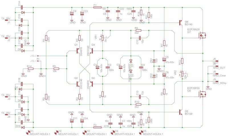
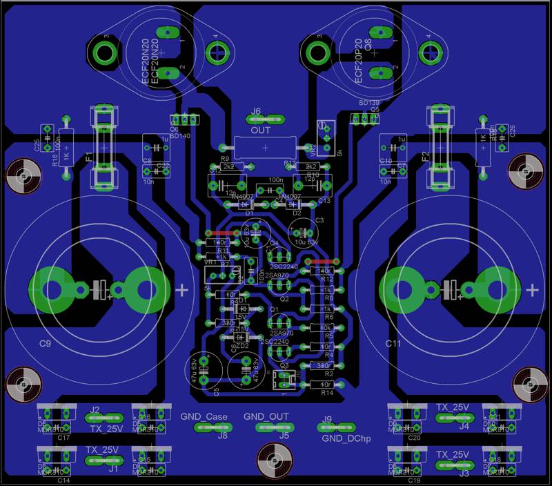
The board mesure 148x130mm. The board allows installation of 50mm large smoothing cap. and is equiped with double rectifier bridge.
I have minor changes in mind around BD139/140
Marc
The board mesure 148x130mm. The board allows installation of 50mm large smoothing cap. and is equiped with double rectifier bridge.
I have minor changes in mind around BD139/140
Marc
Last edited:
I think you have to stick face to face Q1-Q3 and Q2-Q4 like alexmm has done.
They are face to face. I needed toom to route traces. To made them touch, you just need to bent a little leg or to insert à little aluminium pieces between them. In this way you couple them thermaly.
Marc
Wyh dont you turn the caps 180 degrees...and make a simpler GND..??
That's evident as nose in middle of the face (as we said in franch) that I didn't see this simplification of my alex work adaptation. My pcb is overall a output and rectification rearrengement from alexxmm 1.4. As i a have double rectification bridge i don't need anymore some traces on existing on alex pcb and so it allows the smoothing cap rotation. Good advice thanks. It will be done this evenning. Miib have I correctly apply your suggestions for R13/trimmer? Could you advise me with some value for this section. Yesterday I go to my basement stock to pick u somme parts for this one : the two 300va 2x25V toroïdals, 4u screw mallory 23.000µf/ 40V smoothing caps, 2u 230x200x40mm heatsink. As the pcb is ok it will be etched.
Marc
Last edited:
I have not done simulation with the BD 140/139 pair.. so I think you must experiment a little..
You can measure the current in the output stage over the fuse..With my driver set simulation suggests something like 250 ohms...(I would use the trimmer to find the right value an than change to a fixed resistor)
Also the resistors setting the Driver stage current can vary a little.. in my simulations (with different drivers) 140 ohm gives app 20 mA which will be just fine..
good luck.
- Status
- This old topic is closed. If you want to reopen this topic, contact a moderator using the "Report Post" button.
- Home
- Amplifiers
- Solid State
- Simple Symetrical Amplifier