.........Increasing the quiescent current to around 1.2 amps does change the order to even and lowers THD from 1.6% to 0.4%
this is 84W of output dissipation for a maximum ClassAB output of 36W and about 24W of ClassA into 8r0..... I should have qualified it, at an output swing of 24V peak.
You are suggesting a very high bias ClassAB amplifier.
Andrew, the efficiency of class A is very low, power loss can be as high as 75% that is why high power class A is not that popular simply because the power supply and heat sink is uneconomical in relation to output power. But it does sound nice, so the toss-up remains whether irritating the neighbors is more fun than listening to music.
Hi, I am back guys, nice activity is going on, very well.
Thanks for the sch drawn and corrected, maybe it is really more understandable to someone than mine. Since I am on vacations I couldn't make it in P-CAD so hand drawing was a nice alternative.")
I agree for those resistors to be 1W although standard 1% metal film are specified to 0,6W but for the board layout it is better if there is a space to place 1W resistor.
OK, since the schematic has been changed, let's change the "more legible one" too. Also, I propose to use the 1W parts for R3 & R18 since they dissipate about 400mW (20V * 20mA).
Thanks for the sch drawn and corrected, maybe it is really more understandable to someone than mine. Since I am on vacations I couldn't make it in P-CAD so hand drawing was a nice alternative.
I agree for those resistors to be 1W although standard 1% metal film are specified to 0,6W but for the board layout it is better if there is a space to place 1W resistor.
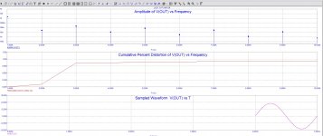
Odd order artifacts is a little on the high side. H3, 5, 7 and 9 contributes most of THD. Increasing the quiescent current to around 1.2 amps does change the order to even and lowers THD from 1.6% to 0.4%
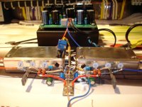
When I listened to one channel the quiescent current was app. 200 mA and the peaks were within +/-10 Vp on 8ohm speaker. I admit I didn't notice any kind of distortion but certainly not that much you got from the microCAP.
Two steps can be done to improve the THD value in sim or in real:
Please try to place current sources instead of 1k resistors in your simulation, I mean 1k resistors supplying app. 15 mA current from +/- 15V to the emitters of the input pair.
Also one possibility to lower distortion is to use standard one BJT zener instead of only resistor for bias adjustment.
In that case we stabilise current and voltage around input pair thus enable them to work in nice linear conditions no matter the level of the input signal amplitude.
Hi Lazy Cat, any reason for using power transistors. In fact you can use the same small signal devices throughout. Alex are heat sinks necessary, these transistors hardly dissipate 50 mW.
Cascode BF transistors have 75mW quiescent dissipation to max. 100mW at working conditions, so small signal transistors could be used but only if we gain something here regarding distortion or noise improvement.
Also please check in sim what the results would be if we lower the value of feedback resistors to 47ohm and thus higher the gain to x22 (+26dB).
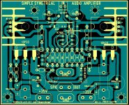
...... few minors changes , and you can see the new PCB rev.1.1
It was my plesaure to do this board , but can be layout again if not ok
Alex.
Your pleasure is our fascination. Really very nice board you've made here Alex, congratulations.

For now please wait for some results of testing to see if there is some improvement we can make and than adjust the layout to final version.
How will it perform as a pre-amp.. with the smaller.. to220 lateral fets (SK216/SJ79) in the output..I believe the lower input capacitance will lead to lower distortion.. and even higher bandwith
Yes that could be the reason for high THD levels in sim Nico made, the model including power laterals as outputs.
In my test rig as you can all see I used BIGBT power outputs which have low input capacitance of IRF610/9610 at the input and two powerful BJT's at the output. Maybe my BIGBT outputs are the reason for lower distortions and very pleasant musical presentation I experienced.
Attachments
Few thoughts about a quiescent current of the outputs in correlation to quiescent current of the input pair. The higher the ratio the better THD results we get, so increasing one or decreasing the other would give better result ... or to find output devices with higher transconductance, mhmm ...
Lazy Cat, at what Iq did you listen to the amp?
Nico Ras, what is the distortion profile at 1 watt?
Thanks,
Hi Samuel
I get H3 sitting at 0.83% @ 1 watt (@1kHz and 2% @1 watt @ 10kHz.
Lazy Cat is right in saying he does not hear such high distortion. It is very difficult to hear distortion of 2% or more listening to music even-though you may hear this quite easily when listening to a pure sine wave.
I am not too perturbed about the high odd order distortion in this simple amplifier. In fact with the relatively high odd order distortion it would sound subjectively crisp and detailed to most listeners.
The amplifier frequency response is in fact very high with the -3 dB point at 2.35 MHz. The phase margin at 17 MHz is still great at 61 degrees, so stability is not at all a problem. It remains perfectly stable and no hint of oscillation driving pure capacitive load of 10uF.
The slew is 115V/uS and is perfectly symmetrical once the off-set has been nullified.
Overall, I would say a very worthwhile amplifier project for DIY, and attempting to turn it into "high-end" would complicate it far too much.
I would leave it as is. Well done Lazy Cat you deserve applause.
Nico
Nico
Lazy Cat,
I have run another SIM using only small signal transistors, THD dropped slightly to 1% at 10kHz.
-3dB bandwidth changed slightly to 2.018MHz but phase margin went up to 80 degrees and the slew rate improved to 156V/uS (interesting)
Power dissipation on the small signal transistors are <20 mW, so I can safely say that using BC550/560 through-out in the front is fine.
I have also briefly looked at increasing the gain. It is better increasing the value of the feed-back resistors to 2.2K than halving the shunt resistors as reducing the shunt resistor values introduces cross-over distortion.
- Status
- This old topic is closed. If you want to reopen this topic, contact a moderator using the "Report Post" button.
- Home
- Amplifiers
- Solid State
- Simple Symetrical Amplifier