Mr.shaan, lc. ssa amplifier can be set klass a, anything that changed? i want to assemble the amplifier ssa in setting klass a. I own the following mr.nafiri assemble pleasant sound amplifier ssa ears, and sounded good and clear ... I myself also feel happy after hearing the sound the sound of the amplifier ssa
Mr.shaan, lc. ssa amplifier can be set klass a, anything that changed? i want to assemble the amplifier ssa in setting klass a. I own the following mr.nafiri assemble pleasant sound amplifier ssa ears, and sounded good and clear ... I myself also feel happy after hearing the sound the sound of the amplifier ssa
hi sofianirawan.
Of course the ssa can be class-a by placing more diodes in series with the existing biasing diodes. But I personally doubt there will be any sonic difference or reduction of THD.
Congrats on your SSA build.
Class A is better to keep a listening room warm atmosphere.Of course the ssa can be class-a by placing more diodes in series with the existing biasing diodes. But I personally doubt there will be any sonic difference or reduction of THD.
(Why the hell this class A audiophile legend ?)
Class A is better to keep a listening room warm atmosphere.
Don't say. A pair of DOZ can give a mighty 15kelvin boost in room temp in 1 hour. Perfect room heater in a christmas night.
Why the hell this class A audiophile legend ?
Coz those audiophile x-spurts couldn't find a way to minimize the crossover distortion other than sinfully using lots of unholy negative feedback which is destined to "suck the soul out of the music". Poor kids... if only they didn't assume the feedback signal cycles inside the input stage... alas.
No matter, they've got train-loads of bucks so they can solve the problem the global-warming way.
")
Hi!
Remember some posts ago I posted a spice simulation that didn't look too good?
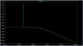
Turns out I had a problem with the LTSpice directive. Now I got it right and the distortion spectrum at 20kHz is attached bellow. Looks much better!
THD @ 20kHz @ 22V is about 0.02%.
I also had reported an oscillation problem. Gate resistors + input snubber (20pF // 3.3K as recomended by Keantoken) + 680pF input filter cap + a new, shorter, shielded, decent input cable, and the oscillations are completly gone! It's obvious to me now the culprit was that stupid inductive long cable. Gave the cable to the cat. He's having lots of fun with it! The amp is rock stable!
This little amplifier has the most beautifull extended highs I have ever listen to, an envolving midrange and unbelievable strong bass! Thank you Lazy Cat, Shaan and all ther others who worked together to design this wonderfull piece of art! Thank you, thank you, a billion thanks!
Remember some posts ago I posted a spice simulation that didn't look too good?
Turns out I had a problem with the LTSpice directive. Now I got it right and the distortion spectrum at 20kHz is attached bellow. Looks much better!
THD @ 20kHz @ 22V is about 0.02%.
I also had reported an oscillation problem. Gate resistors + input snubber (20pF // 3.3K as recomended by Keantoken) + 680pF input filter cap + a new, shorter, shielded, decent input cable, and the oscillations are completly gone!
It's obvious to me now the culprit was that stupid inductive long cable. Gave the cable to the cat. He's having lots of fun with it! The amp is rock stable!This little amplifier has the most beautifull extended highs I have ever listen to, an envolving midrange and unbelievable strong bass! Thank you Lazy Cat, Shaan and all ther others who worked together to design this wonderfull piece of art!
Thank you, thank you, a billion thanks!Attachments
Last edited:
The 3.3k is in series with the 20pF, and this goes between the input and ground. You put them in parallel?
No amp should have problems with an inductive source impedance; all sources are inductive. But many of them do. I would provide the optimal input compensation network but I don't know which specific version you're using.
No amp should have problems with an inductive source impedance; all sources are inductive. But many of them do. I would provide the optimal input compensation network but I don't know which specific version you're using.
Sorry, no I meant to say 20pf in series with 3.3k.
The cable was really bad. I believe it was the main culprit. With a short shielded cable connecting the DVD player to the amp there's no oscillation I can perceive in the AM radio and the sound is amazing. I need yet to figure out how I'm going to connect the computer audio out to the amplifier, they're not that close.
I'm using Shaan version of the SSA.
If the cable is short and there is minimal inductance to react, it should work fine, and can sound great. For a designer though, oscillation with long cables is a liability that should be corrected.
The problem could be your source. I think you should try a buffer between your computer and cable. Soundcard outputs may have several hundred ohms output impedance. A strange idea that popped into my head is using 300 ohm RF ribbon cable inside grounded metal conduit, but that's just strange.
The problem could be your source. I think you should try a buffer between your computer and cable. Soundcard outputs may have several hundred ohms output impedance. A strange idea that popped into my head is using 300 ohm RF ribbon cable inside grounded metal conduit, but that's just strange.
I did try my preamplifier between the pc and the amplifier. Although the oscillations decreased and the sound got better it didn't make the problem go away completly. In fact when I raised the volume knob the oscillations also raise in intensity.I think you should try a buffer between your computer and cable.
I did try my preamplifier between the pc and the amplifier. Although the oscillations decreased and the sound got better it didn't make the problem go away completly. In fact when I raised the volume knob the oscillations also raise in intensity.
Was this before inserting the input network or after? A quick, short comparison with Symef amp would be appreciated. Thanks.
After inserting the snubber. Without it it's even worst. Maybe I should try a different RC constant.Was this before inserting the input network or after?
Subjectively speaking, both the amplifiers are very, very good sounding. The Symef has a warmer sound - perhaps more "tubey" - sweet, with lots of "texture" and "body". It reminds me of the cosiness of a fire place in the winter. The SSA is cleaner, more forward sounding, more transparent, more "fierce" (strong deep bass) and with highs more extended than the Symef. The soundstage of the SSA is bigger than the Symef's. It's also less forgiving of bad recordings.A quick, short comparison with Symef amp would be appreciated. Thanks.
It's easy to fall in love with any of these amps but I believe they will appeal to different people.
Subjectively speaking, both the amplifiers are very, very good sounding. The Symef has a warmer sound - perhaps more "tubey" - sweet, with lots of "texture" and "body". It reminds me of the cosiness of a fire place in the winter. The SSA is cleaner, more forward sounding, more transparent, more "fierce" (strong deep bass) and with highs more extended than the Symef. The soundstage of the SSA is bigger than the Symef's. It's also less forgiving of bad recordings.
It's easy to fall in love with any of these amps but I believe they will appeal to different people.
Thanks Paul. This is one of the best posts here; honest and giving credit where it is due. Keep up the good work. Now I've got work to do.
Lazy cat,
Very nice design, lots of great sonics to be found in Current feedback designs. I've been an adherent to the symmetrical CF circuits as of the last year plus, and dual feedback loops, one for each positive and negative half. Though after reading the nocompensationaspect, even though it may not be external compensation is always internal due to in any semiconductor cob or fet it's output capacitance which is the equivalent of a cap to ground. Once these cf circuits are nailed its some almost ethereal sounds!
Colin

The behavior of Shaan's schematic changes a lot depending on which BD139/140 is used. ST, Phillips, Fairchild, OnSemi are all different, some of them markedly inferior. The size of Cob on some of them makes the 5pF miller caps laugh. Putting these parts on a schematic without specifying the vendor is a bad idea.
My initial guess of 20pF/3.3k was pretty darn close. Depending on the VAS you use, the best value ranges from 2.2k-3.3k.
However, Shaan's original 1k/10k//22p input network works well enough that there should not be any potential for oscillation with an input cable, so I think the problem must be somewhere else. Counterfeit transistor? Perhaps Shaan used Fairchild or OnSemi VAS and you used Phillips VAS resulting in a faster, less stable amplifier?
I'm using CDIL BD's. Are they inferior? Could they cause oscillations?The behavior of Shaan's schematic changes a lot depending on which BD139/140 is used. ST, Phillips, Fairchild, OnSemi are all different, some of them markedly inferior. The size of Cob on some of them makes the 5pF miller caps laugh. Putting these parts on a schematic without specifying the vendor is a bad idea.
My initial guess of 20pF/3.3k was pretty darn close. Depending on the VAS you use, the best value ranges from 2.2k-3.3k.
However, Shaan's original 1k/10k//22p input network works well enough that there should not be any potential for oscillation with an input cable, so I think the problem must be somewhere else. Counterfeit transistor? Perhaps Shaan used Fairchild or OnSemi VAS and you used Phillips VAS resulting in a faster, less stable amplifier?
I replaced the 20pF cap by a 680pF one to serve as input low pass filter (with the 1k resistor). Them I added in parallel with the 680pF cap a 3.3k resistor in series with a 20pF capacitor to serve as snubber. Am I doing this right? Should I keep the 680pF as input filter or only the snubber parts? And where should the snubber be placed - at the pcb or soldered at the input RCA's?
Thank you.
Last edited:
Hi Keantoken. 
I use either CDIL or BEL parts for VAS. And for the input and cascode, Philips.
My protoboard and later the PCBs didn't cause any oscillation or any noise in my radio(yes I use this trick too), even without any Cdom at all, so the 5pF silver mica caps were just luxory, for me .
Initially I used a 22pF at input, but the ear-on-speaker test showed evidence of some CRT buzz. So decided to use a decent 2KV ceramic 100pF and all's well since then(with a well shielded cable which is more than 5m long, from PC to amp).
Also, I decided not to use the -16(high gain) suffix labeled parts for the BD pair, went the cheap way.
However, as I recently posted, the amp can rectify a lot of MW/SW signals when the input is disconnected from source and touched with finger or my twizzers.
Happy listening.
shaan
I use either CDIL or BEL parts for VAS. And for the input and cascode, Philips.
My protoboard and later the PCBs didn't cause any oscillation or any noise in my radio(yes I use this trick too), even without any Cdom at all, so the 5pF silver mica caps were just luxory, for me
.Initially I used a 22pF at input, but the ear-on-speaker test showed evidence of some CRT buzz. So decided to use a decent 2KV ceramic 100pF and all's well since then(with a well shielded cable which is more than 5m long, from PC to amp).
Also, I decided not to use the -16(high gain) suffix labeled parts for the BD pair, went the cheap way.
However, as I recently posted, the amp can rectify a lot of MW/SW signals when the input is disconnected from source and touched with finger or my twizzers.
Happy listening.
shaan
So, I would really like to build the very basic BJT version, based off of the schematic posted. Just wanted to ask a few questions first:
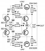
1. The three 1uF caps look like electrolytic's. Is that right?
2. The BC550/560's need to be strapped face to face?
3. The BD139/140's need to be on main heatsink?
Now for the big question. I already have a few different power transistors. They are:
1. Toshiba 2SC3281 / 2SA1302 (original)
2. Toshiba 2SB755 / 2SD845 (original)
3. NEC 2SD588 / 2SB618 (original)
I was hoping not to have to buy new power transistors. I'm also not to the point technically where I can tweak values in the schematic to be able to use these transistors, (still a newbie), but getting much better at following a schematic and building. I was hoping someone could point me in the right direction. I'm thinking the 3281 / 1302's would be the best bet. Advice?
Tom
Attachments
- Status
- This old topic is closed. If you want to reopen this topic, contact a moderator using the "Report Post" button.
- Home
- Amplifiers
- Solid State
- Simple Symetrical Amplifier