thank you Shaan,
here it a good read about howto reduce your electrolyte C input distortion
http://www.sg-acoustics.ch/analogue_audio/power_amplifiers/pdf/audio_power_amp_design_comments.pdf
Don't quite get this article - it says that electrolytic capacitors with substantial voltage across them cause distortion and the solution is connect another electrolytic capacitor in parallel but reversed.
I thought reversed electrolytic capacitors with substantial voltage across them tend to explode.
So don't see the practical use of this advice
Can anyone shed some light on this ?
mike
Hi mike.
I used a bipolar electrolytic at input.
I won't reverse bias an electro with high voltage placing it parallel to the forward one, I have seen a couple of electros explode this way, loudly.
How about opposite, but in series?
Rough guess is that forward cap will protect the other from dangerous AC current.
Shaan it's nice that you're pleased with SSA in its basic form, not alone though, there' Nico and some others DIY-ers too enjoying this version. I listened this one for quite some time too, but when I brought it to our club where's many well renowned amplifiers present, it was clear from the first moment on that was not in their league. After installing CCS-s into SSA, we listened it again and suddenly all well renowned amps from before were simply not in SSA league. But yes, of course CCS-s have to be top performers here, meaning having modulation suppression better than -100 dB according to nominal current, leading to use fet cascodes in CCS. I'm sure someday you'll try it too. 
Interesting finding. I did not listen to my BJT version without the CCS, as I was not happy with the thermal stability of the resistor source. But I can say that I don't find the final version to be harsh or irritating in the least. Given the current demand put on the VAS by the output BJT devices, I would expect some resulting distortion, at least at high output levels (which I don't need for my 100+ dB speakers). The amp is not euphonic or warm, but clean and natural sounding. So whatever distortion is there at my listening levels is benign (I should measure it one of these days).
You probably used LC's CCS, with TLC/jFET/SSM parts. I didn't. I will, later. I do believe that the LC CCS sounds good.
For a simple low parts count amp, this one is very well behaved. The thermal drift is more than other amps I have but well within any practical requirement. No turn on or off thump and very quiet (no noise with my ear at the mouth of the waveguide). The simple version is not suited as is to commercial use. For that it needs the extra bells and whistles like input cap, circuit/speaker protection, etc.. But this is DIY and I don't need them.
Yeah. I install a 1 second time-delayed relay at the output in the amps I make for my customers. This ensures "thump" free turn-on, even for an LM1875 which has inevitable "thud" at turn on.
BTW, how are the output FET crew measuring bias current. Do you have a low value resistor in the power rail or drain for measurement purposes?
Sheldon
1ohm in PS rails to whole amplifier, 10ohm to front end and VAS, no resistor in drains. 1ohm current minus 10ohm current equals FET current.
")
Last edited:
Shaan it's nice that you're pleased with SSA in its basic form, not alone though, there' Nico and some others DIY-ers too enjoying this version. I listened this one for quite some time too, but when I brought it to our club where's many well renowned amplifiers present, it was clear from the first moment on that was not in their league. After installing CCS-s into SSA, we listened it again and suddenly all well renowned amps from before were simply not in SSA league. But yes, of course CCS-s have to be top performers here, meaning having modulation suppression better than -100 dB according to nominal current, leading to use fet cascodes in CCS. I'm sure someday you'll try it too.
I believe you. I will try it ASAP.
.......
Alex.
Hi Alex
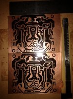
Can you give copper surface can be printed? ( post #559 )
Last edited:
Hi harry.
The regulated voltage is fed to the bases of the cascode transistors for maintaining constant voltage fed to the collectors of the input bjts making them act like constant current sources. The cascodes pass the collector AC current of the input bjts to the next VAS stage with minimal modification as they are used in common base configuration. But any noise present in the cascodes' bases will also be transfered to the VAS, where the noises will be amplified too. That's where the idea of a regulated supply with low impedance(by virtue of the capacitor parallel to the zener) comes into act. It was used in the first post, and so far has been proved to be an essential part of SSA. Poor regulation in this supply may result in hum/noise and maybe even oscillation.
Although a 'beast with a romantic heart', SSA is also tender and sensitive to the power 'she' is fed, should be of very pure yield and filtered of all contaminants, if main PS is the food that she'll eat, then the cascode supply is the air she'll breath, so take care.
IMHO, main PS regulation for the front stages isn't necessary, but you can add it without any problem.
Last edited:
Dear Shaan,
I've transfered your peeceebee layout to board and reversed text so it will read correctly with toner transfer metod. Is this correct?
WOW
Yes this is correct. I have yet to build it myself so am VERY excited after what you just showed me!


ALL THE BEST FROM ME!
Dear Shaan,
I've transfered your peeceebee layout to board and reversed text so it will read correctly with toner transfer metod. Is this correct?
Hi naf

hehehe you're damn fast, faster than Shaan on this particular case.

Very nice peeceebee leads to another irreversible SSA user.

Hi Alex
Can you give copper surface can be printed? ( post #559 )
Hi 400kg
Right choice, SSA BIGBT peeceebee.
Enjoy


Thank you dear Shaan.
WOW
Yes this is correct. I have yet to build it myself so am VERY excited after what you just showed me!
ALL THE BEST FROM ME!
I'll etch in next to 2 day.
Hi LC, thank you.Hi naf
hehehe you're damn fast, faster than Shaan on this particular case.
Very nice peeceebee leads to another irreversible SSA user.
Shaan,
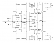
Was the pcb lay-out done by naf follows the attached schematic? Was the lay-out for toner transfer for share?
Thanks!
Attachments
Shaan,
Was the pcb lay-out done by naf follows the attached schematic?
Not entirely. The schematic for the layout is in post 3056. Link:- Post 3056
Was the lay-out for toner transfer for share?
Thanks!
Yes. Have fun.
Does the RF attenuation cap (Post3056) need to be that low in value @ 22pF?
Has anyone tried doubling it?
Or quadrupling it?
Or just jumping straight to 470pF to hear if any of the treble information in the audio signal gets cut off?
Which of the Grounds in the schematic need to be connected to the Signal Ground?
Has anyone tried doubling it?
Or quadrupling it?
Or just jumping straight to 470pF to hear if any of the treble information in the audio signal gets cut off?
Which of the Grounds in the schematic need to be connected to the Signal Ground?
- Status
- This old topic is closed. If you want to reopen this topic, contact a moderator using the "Report Post" button.
- Home
- Amplifiers
- Solid State
- Simple Symetrical Amplifier