Any reason for not using BF245B and 2N5486 JFETs in the SSA BIGBT HP? Just asking as I have them, as well as 2N5462. Moreover, the voltage rating of 2N5459 is lesser than 2N5486.
SSA is predecessor of TSSA, j-fets were implemented much later to possibly improve the design, speaking of sound quality. More about this could be told later on, after CSA's listening tests will be performed.
Although this question belongs to the TSSA thread, is the 10K NTC the only heat sensing device in TSSA BIGBT HP?
Thanks.
Yes, it will be precisely tuned to correct tempco with serial and parallel resistors. Major improvement is its capacitance to the heat sink, which will be few pF only.
")
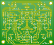
I tried to draw a PCB which will look like the attachment.
Dimensions:- 3.5" X 2.8"
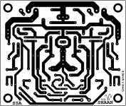
Currently rendering the bottom artwork for toner transfer process. Will upload once done and checked for errors.

Nice drawing Shaan

What about CCS-s? Wouldn't it be nice to have them onboard?
I wish we had such nice toroids available here.
Well there is hope, as the net says, some companies have started mass production and soon the story is going to turn better...
You have SHILCHAR R-Core made in India. Betters any toroid in any respect.
Yes.What about CCS-s? Wouldn't it be nice to have them onboard?
What about CCS-s? Wouldn't it be nice to have them onboard?
Yes from me too - Having everything on the one PCB would give consistent results. Hint to anyone who has board lay out skills.
yes! please Shaan.. include CCS onboard.
Yes the BJT CCS has an instant effect on the amplifier from thermal stability to noise performance. But, for long hours of listening, NO GOOD.
For me, the CCS fed SSA sounds noticeably more crisp than the resistor fed SSA. But after a while it makes the music sound strange(!). "Clinical" would be the closest word to my feelings, although I suspect high order harmonics too. I don't have o'scope and other sophisticated instruments for juggling with it in a "standard" way, so it was simply removed from the board and the resistors were re-placed. Then-and-there the pleasing and enchanting SSA sound was re-established. The CCS was re-connected again a few days later and the fatigue came back. Interesting, but not a happy experience. As a result it was permanently removed.
Still, I do not discourage anybody to use it; I just expressed my experience with it, the case may be different with others.
Perhaps LC's well-tested jFET+SSM+TLC based CCS is the only sonically superior alternative to the resistor.

BTW, The layout for my pee-cee-bee (or whatever it may look like) is ready and will be uploaded shortly.
Rookie job, please be gentle...
Some mods:
1. There's an input cap, everybody knows why. It's an electro ; but trust me once the SSA is up and running, it vanishes.
2. Fixed FET bias of ~150mA with two 1N4148(only 1058/162 tested, ECX not).
3. 10ohm after 1N4007; apparently lowers turn-on thump/hum.
4. 1K+22pF input RF filter.
5. Couldn't eliminate the only one jumper. Sowy.
6. Simple potentiometers; no multiturn. As I found it unnecessary for setting the offset.
7. 1K in series with pots to protect them in case accidentally both set to lowest resistance.
8. Zobel added(of course).
9. 1M before input cap removed. Pretty unnecessary if you ask me.
10. Front end and VAS bias can be varied with changing 1K2 resistor's value, but if the specified BJT's are used then it should not be necessary. Bias with 1K2 measures 4.5mA through inputs and 15mA through VAS.
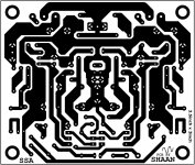
Both layouts are the same, but the one in the right is a little style-ish having fancy pads and lots of copper.
Comments welcome.
PS. The zip contains higher resolution pics of the layout in PNG format.
Some mods:
1. There's an input cap, everybody knows why. It's an electro
; but trust me once the SSA is up and running, it vanishes.2. Fixed FET bias of ~150mA with two 1N4148(only 1058/162 tested, ECX not).
3. 10ohm after 1N4007; apparently lowers turn-on thump/hum.
4. 1K+22pF input RF filter.
5. Couldn't eliminate the only one jumper. Sowy.
6. Simple potentiometers; no multiturn. As I found it unnecessary for setting the offset.
7. 1K in series with pots to protect them in case accidentally both set to lowest resistance.
8. Zobel added(of course
).9. 1M before input cap removed. Pretty unnecessary if you ask me.
10. Front end and VAS bias can be varied with changing 1K2 resistor's value, but if the specified BJT's are used then it should not be necessary. Bias with 1K2 measures 4.5mA through inputs and 15mA through VAS.
Both layouts are the same, but the one in the right is a little style-ish having fancy pads and lots of copper.
Comments welcome.
PS. The zip contains higher resolution pics of the layout in PNG format.
Attachments

If on the oscilloscope, the current is flat whatever the signal level, there is no question to ask. Whatever it sound "clinical" or not, that is the way it *has* to sound.For me, the CCS fed SSA sounds noticeably more crisp than the resistor fed SSA. But after a while it makes the music sound strange(!). "Clinical" would be the closest word to my feelings, although I suspect high order harmonics too.
Just measure the current, and, if the measures are good, it it the resistor version witch has a problem.
May-be, too, the problem is the wiring lengths between the CSS and the board ? CSS are high impedance by definition.
I think this is why it is generally good to go with good engineering principals rather than just go by hearing - sometimes a genuine improvement can actually make the system as a whole sound worse because the extra clarity can highlight a problem elsewhere.
This may mean that the process of improvement may not always feel that comfortable but it is worth persevering because in the end, when all is done well, the sound will be great.
In this instance the CCS is preventing various kinds of PSU noise being injected into the most sensitive part of the circuit ( the FB junction ) Any noise injected here gets amplified along with the signal so it hard to see a downside to using a well designed CCS here.
Last edited:
If on the oscilloscope, the current is flat whatever the signal level, there is no question to ask. Whatever it sound "clinical" or not, that is the way it *has* to sound.
Just measure the current, and, if the measures are good, it it the resistor version witch has a problem.
May-be, too, the problem is the wiring lengths between the CSS and the board ? CSS are high impedance by definition.
The currents have been measured many times, good. But only the steady-state current, not AC, as I already said I don't own a scope. The CCS has much better behavior in this respect than the resistor version. But what a shame, it doesn't sound good at all. So, it is the CCS which has the problem - bad musicality.
I think this is why it is generally good to go with good engineering principals rather than just go by hearing - sometimes a genuine improvement can actually make the system as a whole sound worse because the extra clarity can highlight a problem elsewhere.
This may mean that the process of improvement may not always feel that comfortable but it is worth persevering because in the end, when all is done well, the sound will be great.
In this instance the CCS is preventing various kinds of PSU noise being injected into the most sensitive part of the circuit ( the FB junction ) Any noise injected here gets amplified along with the signal so it hard to see a downside to using a well designed CCS here.
Agree. But, the CCS I used isn't LC's standard SSA CCS and it's not "well designed" and sounds less elegant than the resistor, not worth considering it a drop-in replacement, which LC's CCS is.
I have clarified in my earlier post that the CCS has instant noticeable "improvements" on the sound, but after an hour the thing turns bitter, with no bad behavior in the physicals, i.e. heat, bias, offset, noise.
I listen for long, almost all day, to my resistor SSA in medium volume while doing work or studying, and it doesn't disturb me. So I keep it.
your artworks isSome mods:
1. There's an input cap, everybody knows why. It's an electro
2. Fixed FET bias of ~150mA with two 1N4148(only 1058/162 tested, ECX not).
3. 10ohm after 1N4007; apparently lowers turn-on thump/hum.
4. 1K+22pF input RF filter.
5. Couldn't eliminate the only one jumper. Sowy.
6. Simple potentiometers; no multiturn. As I found it unnecessary for setting the offset.
7. 1K in series with pots to protect them in case accidentally both set to lowest resistance.
8. Zobel added(of course
9. 1M before input cap removed. Pretty unnecessary if you ask me.
10. Front end and VAS bias can be varied with changing 1K2 resistor's value, but if the specified BJT's are used then it should not be necessary. Bias with 1K2 measures 4.5mA through inputs and 15mA through VAS.
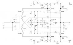
dear Shaan, would you update shcematic to reflect mods on your peeceebee artwork?
I wish we had such nice toroids available here.
Well there is hope, as the net says, some companies have started mass production and soon the story is going to turn better...
I have found that with simple PSU designs EI transformers sound much better than similar spec toroidals but they may need some screening or more space or put in a separate box to avoid hum pickup.
Yeah, EI transformers will tend to give tighter bass. Problem is size and EMI. In the past I believe that because toroidal radiates less EMI, it should be suitable for low level signal like preamps.
But recently I read that because the problems with big size EI transformer is difficult to solve, toroidal is then more preferred for amplifiers. But for preamps, EI is preferred (I think because many small EI are well built and has less issue than big current EI). Wow! I have never thought of this logic. I think it is logical. Unfortunately I don't build many preamps, and for preamp I use better transformer than EI or toroidal.
But nowadays I'm thinking about the front end of amplifiers which usually use higher voltage than preamps. Don't know if separate windings will bring another issues? If not, then EI for the front end and toroidal for the output?
ADD: another possibility is to add small EI at the end of toroidal winding, then drop the voltage with regulator. But I want to hear why EI is different first. Then designing simple and perfect winding may be possible.
Last edited:
your artworks is
dear Shaan, would you update shcematic to reflect mods on your peeceebee artwork?
Thanks for the kind words.
Here is the schema for the peeceebee.
Attachments
Both layouts are the same, but the one in the right is a little style-ish having fancy pads and lots of copper.
Comments welcome.
PS. The zip contains higher resolution pics of the layout in PNG format.
What No verro board??? I'm shocked
It looks like your finesse transfers well to the pcb art form as well!
Tony.
thank you Shaan,
here it a good read about howto reduce your electrolyte C input distortion
http://www.sg-acoustics.ch/analogue_audio/power_amplifiers/pdf/audio_power_amp_design_comments.pdf
here it a good read about howto reduce your electrolyte C input distortion
http://www.sg-acoustics.ch/analogue_audio/power_amplifiers/pdf/audio_power_amp_design_comments.pdf
I have clarified in my earlier post that the CCS has instant noticeable "improvements" on the sound, but after an hour the thing turns bitter, with no bad behavior in the physicals, i.e. heat, bias, offset, noise.
I listen for long, almost all day, to my resistor SSA in medium volume while doing work or studying, and it doesn't disturb me. So I keep it.
Interesting finding. I did not listen to my BJT version without the CCS, as I was not happy with the thermal stability of the resistor source. But I can say that I don't find the final version to be harsh or irritating in the least. Given the current demand put on the VAS by the output BJT devices, I would expect some resulting distortion, at least at high output levels (which I don't need for my 100+ dB speakers). The amp is not euphonic or warm, but clean and natural sounding. So whatever distortion is there at my listening levels is benign (I should measure it one of these days).
For a simple low parts count amp, this one is very well behaved. The thermal drift is more than other amps I have but well within any practical requirement. No turn on or off thump and very quiet (no noise with my ear at the mouth of the waveguide). The simple version is not suited as is to commercial use. For that it needs the extra bells and whistles like input cap, circuit/speaker protection, etc.. But this is DIY and I don't need them.
BTW, how are the output FET crew measuring bias current. Do you have a low value resistor in the power rail or drain for measurement purposes?
Sheldon
- Status
- This old topic is closed. If you want to reopen this topic, contact a moderator using the "Report Post" button.
- Home
- Amplifiers
- Solid State
- Simple Symetrical Amplifier