Lazy/Nico
looks nice an simple...for practical implementation there are issues around back emf and RF..some are more clever than me on this, but could be that a coil and RF-snubber networks are needed..
Well until now I notice the problem you've mentioned only once - small RF traces, when I didn't put bypass caps (1uF) in parallel to all DC smothing electrolytic caps (zener 1uF bypass should be at cascode BJT's base terminal). Also, since this is very fast CF amp, the rails connection on the PCB right at each output mosfet's drain terminal should be bypassed to GND let say with 0,1uF/100V ML, also as short as possible tracks rule, GND track rounding as RF protection around input connection is recommended, ..., similar as you would design a preamp with ultrafast OP amp. RF or back emf from the speaker with these precaution measures taken will not have any chance.
")
I have been studying Alex's PCB and i think it can be improved on the earthing...the primary ground is at the input, think it ought to be next to the output.. then the input can lifted slightly to avoid dirty GND...
Could well be I'am mistaken though, just a thought..
Together we'll try to find the best PCB version based on your sch, no worries now, just go for it.
Last edited:
Member
Joined 2009
Paid Member
funny you mention silence and working without compensation as well, although i used a 3p3
for slight RF rolloff.
yup, it seems the use of non-LTP has many attractions, better stability and less compensation is a key one
Not me to thank..!!
you brought the circuit idea forward, Nico put a little more gain in..And chose the nice BJT devices...I just scaled it a little and provided some more drive for the Laterals.
Yes, that's basic idea of how DIY forum should work, good design idea pushed forward by forum members will lead us on higher level, contributing to whole DIY community.
SSA 100W
OMG Alex, you found something like an intellectual challenge in this thread ... you're becoming better and better at each new PCB

Thanks Michael , nice schematic , and I was excited to make the pcb .It's something preliminary to final PCB ......or not?
Alex.
OMG Alex, you found something like an intellectual challenge in this thread ... you're becoming better and better at each new PCB
Later this evening I connected a sch from the post #217 to a real 200W power supply, +/-35V, 60mF caps bank to perform some more tests, at least that was the plan. At the end I only managed to make some small changes to Vbe multiplier but for an almost two hours I have listened to a music instead of doing some more measurements/experiments. Situation that happened so rarely in my DIY career - the sound was so good that I forgot to do anything else. The only explanation I can think of, to understand the sound quality presented, lie in the amp's phase-time-frequency characteristics. Sound was so naturally live when I went outside the lab, one could easily think it is the real stuff going in.
Last edited:
Member
Joined 2009
Paid Member
Later this evening I connected a sch from the post #217 to a real 200W power supply, +/-35V, 60mF caps bank to perform some more tests, at least that was the plan. At the end I only managed to make some small changes to Vbe multiplier but for an almost two hours I have listened to a music instead of doing some more measurements/experiments. Situation that happened so rarely in my DIY career - the sound was so good that I forgot to do anything else. The only explanation I can think of, to understand the sound quality presented, lie in the amp's phase-time-frequency characteristics. Sound was so naturally live when I went outside the lab, one could easily think it is the real stuff going in.
Now that IS a great sign of a good amp
How is the treble - any sign of harshness at all ??
I bet Bryston never thought of using a FET as part of the Triple as you've done here. Nice design.
Last edited:
yes, i too think that that is the most beneficial to perceived sound quality and reality, (phase true-ness) and i had numerous events of super reality of reproduced sounds.
trebles in my case (even if rolled off slightly) were smooth as silk and crystal clear and open and transparent. it is more important that the fase remains true even if the amplitude has to decrease. that way also the amplifier stays out of being pushed to keep up, and is not getting a messy response over the complete band, i figure.
one time my bro, who drums, said it sounds stunning real when he was outside while i listened to a drum demo. ofcourse i knew that and that is why i ended up with such kind of amplifiers.
these days i build my amps consciously like broadband video amps, or oscilloscope amplifiers, for that.
getting better.... Like your style...
the 1 pf caps can be removed I just added them for simulation.. to see what what influence PCB capacitance had for stability... as the feedback and output run together for quite a length...
also I think the input pair need to face each other so they can be glued together...
Nico/Lazy/alex
I wonder at bit about input network....This thing has gain all the way to DC.. some sources can have DC..and what about input RF limitation..??
Last edited:
Miib, regarding input DC/LP filter, of course it can be on board, but I have few thoughts about that. SSA works perfectly without any frequency compensation-limitation and that is its charm, you have to hear it and than you will feel the amp with no limitation (except parasitics).
The source normally should have its own freq upper limit so the problems usually comes from the RCA connection cables and their RF suppresion immunity. Since that is different from case to case, I suggest to place simple DC/low pass filter at RCA connector where RF comes into the case. So stopping RF just at the entrance of the case has its benefits, not allowing the RF to flow/induct in to other wires inside the case. On board DC/LP filter would be necessary if we would have PCB RCA connector.
DC filtering is out of the question to my thinking, so it is up to you to choose the right value/qualitiy input series capacitor.
The only explanation I can think of, to understand the sound quality presented, lie in the amp's phase-time-frequency characteristics. Sound was so naturally live when I went outside the lab, one could easily think it is the real stuff going in.
Lazy Cat, I too think that is what makes it sound great, distortions and harmonic spread is far less important, I will be implementing Michael's (MiiB) suggestion over the week-end. The Lazy Cat amp really has the potential to go become a great amp.
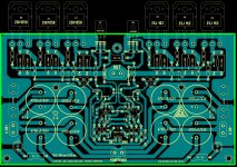
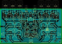
The first PCB was made quickly, but it is better this PCB now ,at least I hope so
Alex.
Alex great work again.
To my opinion, since this more powerfull version PCB is very important for people having more demanding speakers, I will try to make come useful comments-suggestions:
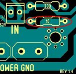
- LED's should be connected at fuse output to correctly signalize no-operation
- MOSFET bypass caps should be 100nF/100V/R5-7,5mm
- input pair (common base BJT'S) should be face-to-face (mandatory)
- 10 ohm GND lift resistor should be connected to the center of GND PWS pin
- there should be two GND faston 6,3 mm pins (one for PWS, another for the speaker neg)
- if we have 8 x 4700uF already on board, there is wise to have 4 rectifier ultra fast diodes too, so AC connection on PCB would be nice
- in the middle of 1N4148 diodes should be multi turn trimmer 500 ohm for the BIAS adjustment
- for two 3,3pF feedback caps pls provide more space-area to be able to put also silver micas R7,5 mm
- delete 1pF, simulation only
- two 1k resistors to supply current to zeners should be 1-2W
- put 1uF/100V cap to each rail just at fuses output
- pls reverse the position of input connector and 2200uF cap
So if you feel free to make these changes we all be happy.

Last edited:
Lazy Cat, I too think that is what makes it sound great, distortions and harmonic spread is far less important, I will be implementing Michael's (MiiB) suggestion over the week-end. The Lazy Cat amp really has the potential to go become a great amp.
I agree completely, especially if one has the source like mine, than you can hear really great stuff in the music.
Attachments
- Status
- This old topic is closed. If you want to reopen this topic, contact a moderator using the "Report Post" button.
- Home
- Amplifiers
- Solid State
- Simple Symetrical Amplifier