Look here why that is so:
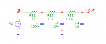
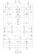
Fig. 1 is a simple 3rd order LP filter
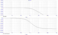
Fig. 2 depicts the frequency response. Notice a phase lag of 180 degrees at 2.84kHz. Does it means a delay 0.5/2.84k = 176 us? NO! Look at the next picture.
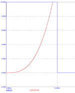
Fig. 3 shows the onset of the step response. Notice that the output starts immediately to rise. Due to a limited resolution, you will see the rising only a few nanoseconds later. Anyhow, it doesn't start to rise 176 us later.
PS: posts were crossing.
Fig. 1 is a simple 3rd order LP filter
Fig. 2 depicts the frequency response. Notice a phase lag of 180 degrees at 2.84kHz. Does it means a delay 0.5/2.84k = 176 us? NO! Look at the next picture.
Fig. 3 shows the onset of the step response. Notice that the output starts immediately to rise. Due to a limited resolution, you will see the rising only a few nanoseconds later. Anyhow, it doesn't start to rise 176 us later.
PS: posts were crossing.
Attachments
Last edited:
yeah - and personally I think this delay CAN affect treble quality - perhaps even upper midrange - but sub bass ?
I accept that you can hear something different and this must be caused by something - but the feedback idea doesn't seem to make sense unless were talking about a temporary loss of damping factor - that could explain loss of bass detail - does that make any sense ?
I accept that you can hear something different and this must be caused by something - but the feedback idea doesn't seem to make sense unless were talking about a temporary loss of damping factor - that could explain loss of bass detail - does that make any sense ?
Yes, but the an amp is not a wire, each device has i/p capacitance ( not to mention the millar cap ) and all the tracks & wires have inductance.
The feedback may get back pretty fast - especially in a current feedback amp, it's the signal coming forward that has a delay.
The feedback may get back pretty fast - especially in a current feedback amp, it's the signal coming forward that has a delay.
All active parts has delays as mikelm says.
An 2N3904 for example has 35nS delay.
http://www.onsemi.com/pub_link/Collateral/2N3903-D.PDF
Page 2 under switching characteristics.
An 2N3904 for example has 35nS delay.
http://www.onsemi.com/pub_link/Collateral/2N3903-D.PDF
Page 2 under switching characteristics.
Oh, my god, i wonder my joke originate such a controversial exchange!
Well. With my SSA 5Mhz flat bandwidth, 1200V/µs slew-rate, and phase response flat up to 400Khz, i'm not so much afraid by any 'delay' at low frequencies in the CR.
It seems right to say that Kick drums, for example, shows the most "energy" and fastest slopes in the response curves. And right to thing that, if the amp is not able to follow the slopes applied to his input, there is a risk to see the ugly TIM appearing in the signal reproduction.
But, if you filter the signal before the input so it is slower than the amp speed capacity, i believe the problem is eliminated.
When i feel a problem in the sub basses, i have the habit to look first around the power supply.
I believe too that Current Feedback, because it is a way to get the fastest response you can get from your parts, is the best way to get so calling *fast* separated and solid basses.
Well, on an amp reproducing the full band, if you increase the slew rate (changing his schematic from voltage to current feedback, as an example) the most noticeable improvement you can hear is, indeed, in the bass response area.
That was precisely to demonstrate all those affirmations that i had made such an experiment, that you can see here: www.esperado.fr - Le crescendo revisité. And interesting to see the impact on both slew-rate (open loop bandwitch) and distortion. Listening experience confirm the measurements.
I wanted to add that most of the controversial aguments about CR here where right. And easy to understand why not contradictory when we understand the feedback principles.Listening experience confirm the measurements.
Studying that from the early beginning of Analog Devices experiments on CF topologies, my religion, about audio amps and preamp design, can be resumed in a single attempt: "Speed" ;-)
Because the SSA feedback topology is (all along with "Error feedback" topology) the best way to get this speed (an most simple than Error feedback) , and can be applied to most of the power amps schematics: Go for SSA.
And to add that it is interesting to consider that, in my experiment about SSA, we have a fantastic increase of the slew-rate, while we do not change a lot the open loop schematic neither the active parts ;-)
Last edited:
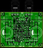
...... few minors changes , and you can see the new PCB rev.1.1")
It was my plesaure to do this board , but can be layout again if not ok
Alex.
What utilisas program?
for relizar these "PCBs"
EXAMPLE: Eagle, proteus, pcb wizard. What do you use? : Confused:
I agree with you about using CF because it is a fast topology and this sounds best but having chosen this topology I think it is best to avoid using too low value resistors in the FB circuit to try to speed things up even further - In my experience the opposite sounds better.
Do others have the same experience ?
Do others have the same experience ?
.... thanks to all for helping me to layout the correct PCB
Alex.
Hi, Alex MM
I just wish the "PCB", without components
to do with the method of the pplancha, "heat transfer"
"Post number 158"
Attachments
Last edited:
Sonnya, Apart from propagation delays of the medium at use (e.g. copper or whatever), the onset of the response isn't delayed. If you keep thinking in terms of delay instead of phase lag, you will never understand why NFB works as it does work.
Sounds like semantics to me. Whatever you choose to call it the voltage rise is delayed so there is a delay - even though it is called current feedback in fact the i/p transistor compares voltages. So if the voltage rise is delayed, there is a delay before the signal gets back to the feedback transistor. - end of story.
Last edited:
less devices less delay... and for current feedback the IP device is the feedback device. That is why the speed increases and why it sounds better... feedback applied this way is simply less intrusive than the typical LTP...where separate devices with different impedance's handles the feedback..
Who said that ?Okay i am stupid
What you said about delay is true. But the problem does not fully rely on that. First Nyquist law will never let-you run an amplifier with a 180° phase shift if any gain ;-)
Second, delay matters with fast changes in the signal, right ? And delay will bring overshoot Agree ? Slew rate limitation and good compensation avoid that. So the real concern is just final slew rate of your amp and flat response with no overshoot..
Where the delay/phase problem is your is when you are working on poles optimization / harmonization.
Last edited:
delay time (or latency) vs phase lag.
A time delay, IOW a latency (caused by long transmission lines or so) is mathematically expressed by: exp(-sT). It delays the arrival of signal at the receiving end by an amount equal to T without altering the amplitude. Thus the onset of the step response is also belayed by T seconds.
OTOH, a phase lag (caused by a LP filter or capacitances of a tranny etc) are expressed by e.g. (1-exp(-sT))/s, which does alter the amplitude, but it does NOT delay the onset of a step response or so.
If you call these crucial differences just semantics, you've missed my point (and fundamentals of FB theory).
Sounds like semantics to me. Whatever you choose to call it the voltage rise is delayed so there is a delay - even though it is called current feedback in fact the i/p transistor compares voltages. So if the voltage rise is delayed, there is a delay before the signal gets back to the feedback transistor. - end of story.
A time delay, IOW a latency (caused by long transmission lines or so) is mathematically expressed by: exp(-sT). It delays the arrival of signal at the receiving end by an amount equal to T without altering the amplitude. Thus the onset of the step response is also belayed by T seconds.
OTOH, a phase lag (caused by a LP filter or capacitances of a tranny etc) are expressed by e.g. (1-exp(-sT))/s, which does alter the amplitude, but it does NOT delay the onset of a step response or so.
If you call these crucial differences just semantics, you've missed my point (and fundamentals of FB theory).
Last edited:
less devices less delay... and for current feedback the IP device is the feedback device. That is why the speed increases and why it sounds better... feedback applied this way is simply less intrusive than the typical LTP...where separate devices with different impedance's handles the feedback..
Hi MiiB
Exactly, could not tell it better even if I tried.

Regards to all

- Status
- This old topic is closed. If you want to reopen this topic, contact a moderator using the "Report Post" button.
- Home
- Amplifiers
- Solid State
- Simple Symetrical Amplifier