Hi LC,
I have read (much was simply scanned) this thread from the beginning and all of the early comment I found indicates that this amp is for me....but in its simplest form. I want to build it, but, with over 2,200 posts, I cannot find the "Official, approved by You" schematic for the amp and PS. IF you know where to find them will you please give the post numbers or repost the .pdfs/drawings.
Very many thanks.
Yes. As a sound engineer, i ask, for my reproduction system to be as transparent and analytic as possible. Reason why i do not look for that kind of "tube sound" able to make agreeable even a disagreeable recording.So it is more about one's priority and preference over music.
I don't believe a low distortion/fast amp produce more agressive treeble. On the contrary, the two things i can notice with my SSA mod is more detailled basses and more natural (smoother) trebles (specially cymbals). Probably due to less TIM. More space too between instruments, they are easier to separate and follow, with less listening fatigue.
As it is the same amp, same VAS, same drivers and same power stage, i credit this change to the slew-rate and distortion improvement.
My high efficiency and very analytic 2 ways satellites are equipped with JBL drivers (and kind similar wooden circular horns as LeCleac''s ones) for the top range, from 1Khz. They do not go high in treble, and my amp was quite fast before. So, it is definitely a question of TIM, not bandwidth.
(For the basses, i run a 48cm JBL in a 500L BR sub, down to 30hz).
About impedance curves of the speakers, they are totally compensated, and the total curve is very linear at 6 Ohms.(less than -+1 Ohm around)
About switching amps, i agree that, if the quiescent current is enough to make them running in class A at normal (medium) listening levels , there is no real improvement to produce more heat in tuning them up to full class A.
About tube amps, one of the reason they sound agreeable is, i believe, because tubes are very fast and have a large linear slope. But, because the output transformer, no one i know is able to reach the definition and dynamic of my actual (SSA like) 135W amp. And my friends said that he has kind of a "tube's" transparency, ease and smoothness.
Back to the roots
provided the model provided by Bob Cordell is correct and the schematic is correct
I get an op of 1.8 amps drain current .
Is that correct?
Try adjusting R11, R12 or R3, R4 to set bias drain current to whatever you prefer.
p.s. preference for this varies. I would suggest 200mA - 500mA
Last edited:
similar to this?
I guess that you are thinking some kind of this way: Current-Drive - The Natural Way of Loudspeaker Operation
and JBroskie too: PS-12 & Trim-1
I am going to check if TDA2040 will beat my Yamaha A1: Transconductance amplifier project - Current-Drive - The Natural Way of Loudspeaker Operation
No it is the correct approach because B*l*I= d2/dt2+ d/dt+....
that is the mechanical motion equation.
All one has to do is to feed a current amp with the output of an "analog computer" ( 3 integrators and one adder ) to cancel out all of the mechanical
constants such as mass compliance...and electrical constants such as resistance and inductivity of the voice coil. So far only swedish co ACE employs this approach. It gets a bit simpler with positive feedback from a resistors in series with the speaker.
of course the real speaker does not follow a simple second order de but it is a simple and easy to implement approach.
I guess that you are thinking some kind of this way: Current-Drive - The Natural Way of Loudspeaker Operation
and JBroskie too: PS-12 & Trim-1
I am going to check if TDA2040 will beat my Yamaha A1: Transconductance amplifier project - Current-Drive - The Natural Way of Loudspeaker Operation
Try adjusting R11, R12 or R3, R4 to set bias drain current to whatever you prefer.
p.s. preference for this varies. I would suggest 200mA - 500mA
If you adjust R11 R12 ( R3 R4 has of course no effect) you reduce the cascode current AND the feedback factor. When the thermally stable op of 100 mA is set, you'll find the cascode also adjusted in class AB .
In the original schematic it is a class A with about 130 Watts power dissipation.
It is possible to adjust the op of the cascodes to zero thus that the switching is
in the cascode. That can drive a BJT class B current amp and in simulation it can be done, but possibly not in practice. because of exponential depednecy
of Vbe.
I guess that you are thinking some kind of this way: Current-Drive - The Natural Way of Loudspeaker Operation
and JBroskie too: PS-12 & Trim-1
I am going to check if TDA2040 will beat my Yamaha A1: Transconductance amplifier project - Current-Drive - The Natural Way of Loudspeaker Operation
Current drive is the natural way because of the motion equation. If the electrical equivalents of the mechanical factors are cancelled out electrically
there is no more resonant frequency no more phase shift no more timing error
of multi way speakers. You don't even need to know the speaker's data.
All you need is a precise microphone and a scope and then adjust every speaker to max rectangle reproduction.
( R3 R4 has of course no effect)
my mistake, I should have said R1, R2
Current drive is the natural way because of the motion equation. If the electrical equivalents of the mechanical factors are cancelled out electrically
there is no more resonant frequency no more phase shift no more timing error
of multi way speakers. ...
but the current makes no sence without the voltage
The elegance of the SSA topology is certainly not that it is just another CF class A, but that it elegantly avoids the need for a second set of power supplies which CF always requires due to poor CMRR.
Replacing the zeners with CS being biased by thermal trak diodes is apparently nice.
No Vbe is required just a resistor or trimmer in Vas. And the diodes are out of the signal path.
Replacing the zeners with CS being biased by thermal trak diodes is apparently nice.
No Vbe is required just a resistor or trimmer in Vas. And the diodes are out of the signal path.
On the contrary, the two things i can notice with my SSA mod is more detailled basses and more natural (smoother) trebles (specially cymbals). Probably due to less TIM. More space too between instruments, they are easier to separate and follow, with less listening fatigue.
As it is the same amp, same VAS, same drivers and same power stage, i credit this change to the slew-rate and distortion improvement.
Hi Christophe, I have a question regarding the SSA-Crescendo and mosfet amps in general.
I have built many mosfet amps to find the best one for my own use. I have an unused Crescendo module that I can easily mod into an SSA_Crescendo based on your circuit. But I'm so reluctant to do that because I had made my mind that the topology used by the Crescendo is not good enough for mosfet outputs.
I have found that my preference towards mosfet amps has high correlation with the strength of the drive for the mosfet outputs. The better the drive, the better the sound.
In term of the drive capability, the crescendo topology (2-stage, high impedance VAS) is very lousy, and so is the popular 2-stage double LTP topology.
The problem is, the SSA is also similarly lousy in that matter. And I have had difficulty to get an acceptable SSA design to replace my Goldmund Mimesis 3.
My question is, is there such thing as too low drive for the mosfet, when I can be sure that the signal is never distorted or switched when the input is tested up to 0.7V. I guess the low drive "might" cause an oscillation that cannot be seen from the chart. But what else should I look for, in term of the minimum drive for the mosfet? The more I aim for low distortion and DC offset, the lousier the drive. The picture I attached is the latest iteration for 2-stage SSA-Crescendo that I did long time ago with acceptable distortion (170mA output bias) but I think will not work in practice. I have also recently given up the basic 2-stage (driver) SSA-Latfet with 56.56V rail (Now I'm working with 3-stage SSA-Latfet).
Attachments
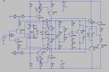
SSA BJT Thermal Trak simpleton version 1
SSA BJT Thermal Trak simpleton version 1
op Q1 Q4... set to 2.6 mA that is about the middle of min noise ( 600µA) and max ft for BC550C
op Q5 Q6 set to 60 mA for best linearity and max fT.
R8C7 R9C8, R18C5 R19 C6, R22 C9 R29C10 lag lead compensation to tweak square performance under varying complex load and optimize reactive distortions.
Q7 has thermal trak diodes D3 D4 in emitter , the R network is to provide constant bias
between 25 and 125 degrees junction temp of thermal trak BJTs Q10 Q12.
This is a first simpleton approach it can be done better.
Attachments
Was mild on ~zero gate current Latfet. Not for BJT output then.
Removed the CCS. This is what I have now. It actually looks pretty good on the scope. A little overshoot, but I guess that some playing with compensation would eliminate it completely. Only problem is stabilizing bias. LC hasn't yet published his thermal comp recipe yet, or have I missed it?
Attachments
Last edited:
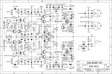
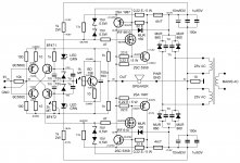
SSA BIGBT HP 1.9
Hi guys
This schematic is working very good. Exact values of the parts are from the real SSA BIGBT HP.
Inner resistance at output terminals is 5,6 mohm at 20 kHz, square waves at 60 Vpp/100 kHz are razor sharp, with no overshot or ringing with or without 4 ohm load connected.
1,5 k NTC is small (3 mm disk diameter) SIEMENS negative tempco thermistor, thermally coupled to input BJT pair. Together with linearization compensation 220 ohm resistor, serves to stabilize VAS 10 mA bias current within tolerance of +/- 0,5 mA.
That's all for now, regards, Andrej
Attachments
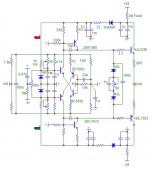
I would like to start building this version (attached).
Any advice or modifications to the circuit?
Could I use BC546/556 in place of BF471/472 pair? Or even 2SA1381/2SC3503?
Is there a PCB layout available somewhere in the thread (even though, I would like to draw one by myself)?
Thank you for this nice project.
Regards,
Max.
Any advice or modifications to the circuit?
Could I use BC546/556 in place of BF471/472 pair? Or even 2SA1381/2SC3503?
Is there a PCB layout available somewhere in the thread (even though, I would like to draw one by myself)?
Thank you for this nice project.
Regards,
Max.
Attachments
I would like to start building this version (attached). Any advice or modifications to the circuit?
Well this version was more or less intelectual exercise nothing more. I do not see the reason why it shouldn't work in reality. Maybe some small frequency compensation capacitor as local feedback to mos-fet would be necessary, but that depends on PCB, complementary parts characteristics symmetry, etc. But this sch would certainly not have even near as good specs as upper sch, one important VAS stage is missing to get a real performance SSA amplifier.
My latest version isn't that much more complicated and if I were you I would choose upper schematic for sure.
I probably don't understand your question. Driver is a high impedance cascode (with a video transistor), over-calculated to supply enough current to the gate holes capacitances of the mosfet, not ? And mine is stable, even on high transients.My question is, is there such thing as too low drive for the mosfet, when I can be sure that the signal is never distorted or switched when the input is tested up to 0.7V. .
Simulation sheet is here: http://www.esperado.fr/images/stories/SSA-Crescendo/SSA-crescendo.zip
Anyway, if your module is still equipped with all parts (some can be difficult to find nowadays) it is not a big deal to modify. Just take care of the resistances of output stage, they have to be non inductive.
Hi, L.C.This schematic is working very good. Exact values of the parts are from the real SSA BIGBT HP.
I believe now, the author of the first post in a thread have now the ability to edit the first message in this forum.
May-be an opportunity to update all interesting or definitive schematics in it ?
- Status
- This old topic is closed. If you want to reopen this topic, contact a moderator using the "Report Post" button.
- Home
- Amplifiers
- Solid State
- Simple Symetrical Amplifier