Hi,
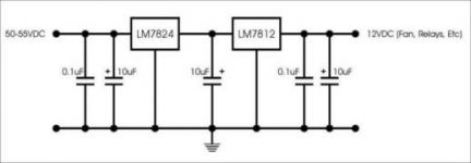
I need to derive 12Vdc from my transformer which has a rectified/filtered output of 55V. Will the attached regulator work? It will only be used to power the fan and relays for the protection circuit. Maximum output current must be around 750mA which I think the regulators can easily handle.
Any comments?
JojoD
Attachments
Oooopppssss!
Hi,
The 7824 would probably "eject" itself out of the pcb!
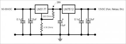
Okay here's a new one.
LM317T Input Output Voltage Diff. (Vin-Vout) = 40V
In this case, my LM317 output is 28V which is set by 220Ohms and 4.7K ohms resistors,
then 55V-28V=27V so I'm below the max input for the LM317T which is 40V.
LM7812T Max Input Voltage = 35V;
in this circuit my input to the 7812 is the output of the 317 which is 28V.
Will this work?
JojoD
Hi,
The 7824 would probably "eject" itself out of the pcb!
Okay here's a new one.
LM317T Input Output Voltage Diff. (Vin-Vout) = 40V
In this case, my LM317 output is 28V which is set by 220Ohms and 4.7K ohms resistors,
then 55V-28V=27V so I'm below the max input for the LM317T which is 40V.
LM7812T Max Input Voltage = 35V;
in this circuit my input to the 7812 is the output of the 317 which is 28V.
Will this work?
JojoD
Attachments
JojoD818 said:sajti,
I tried your suggestion and it worked. i used a tip29c since it was readily available. However, the transistor was very hot, even with a large heatsink. I was only drawing about 500mA.
JojoD
This is OK. If You check the dissipation is: (55V-12V)*0.5A=21.5W But the overall dissipation will be same with the regulators too. You can reduce the dissipation if You put some series resistor before the series-pass transistor. 33-47ohms 15-20W looks OK.
And You can avoid all the regulators with one series resistor:
R=(55V-12V)/0.5A=86ohms. The real value can be 91ohms, with 30W.
Sajti
jojo,
for your circuit with lm317 you need zener diode protection for the lm317 because at switch-on the 40V rating is exceeded until the cap charges up to 15V !
even with resistors you get the same power dissipation, just more in the resistor and less in the device, just to clarify.
you can also use more transistors in parallel to ease dissipation requirements per transistor and get improved heat transfer to the heatsink.
sajti is right, you don't need regulators for fans and relays. these devices are very tolerant of voltage changes and work perfectly with unregulated voltage.
but burning up so much power in a resistor is not very elegant..
better use a second transformer!
or a buck converter.. !
regards
keyne
Just what I thought...
Hi guys!
Adding another transformer for this application is exactly what I'm trying to avoid but still considers it if all else fails.")
As of now, I used two tip29c with a resistor and it seems to be fine. Heatsink is hot but can be touched. Running for 2 hours now with a fan and a couple of relays, drawing around 450mA. Seems ok now.
Thanks guys!
JojoD
Hi guys!
Adding another transformer for this application is exactly what I'm trying to avoid but still considers it if all else fails.
As of now, I used two tip29c with a resistor and it seems to be fine. Heatsink is hot but can be touched. Running for 2 hours now with a fan and a couple of relays, drawing around 450mA. Seems ok now.
Thanks guys!
JojoD
Maybe this is simpler
I don't like this solution of generating heat to move a fan whose purpose is to remove heat -- not particularly a "green" solution.
National Semi has an application note on using the LM3524 controller for fan speed
http://www.national.com/an/AN/AN-292.pdf
with a little creativity you can configure the LM3524 to both act as a buck regulator, or a flyback converter and fan speed controller. Just use an ohmic sensor in the feedback loop.
The garden variety LM3524 will take up to 40 Volts so you will need to use a little beefier transistor to stand off the higher voltages.
The IC looks good, but it's will be too complicated compare with the simple emitter follower regulator.
I made a circuit to regulate the fan speed with the heatsink temperature. This circuit drive the 12V fan with 5V when the heatsink is cold. With this voltage the fan runs quiet. When the heatsink warming up, the circuit starts to increase the driving voltage up to 12V.
The circuit works well in some amplifiers over the years, but it's too complicated compare to the simple regulator.
Sajti
well, fwiw
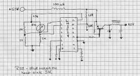
i drew out this circuit -- using 1/2 of the LM3524's output to drive the switching transistor. the resistors in the bridge with the NTC resistor should be adjusted so that you get a maximum 25% duty cycle on Collector "A" this will put about 13.8 volts on the fan motor. With the switching setup you need a 100uH inductor on the lead coming into the fan controller to keep the switching transients from propagating back into the amplifier. the advantages are low parts count and high efficiency -- the most expensive thing is the thermosensor -- less than $2 from Digikey.
i drew out this circuit -- using 1/2 of the LM3524's output to drive the switching transistor. the resistors in the bridge with the NTC resistor should be adjusted so that you get a maximum 25% duty cycle on Collector "A" this will put about 13.8 volts on the fan motor. With the switching setup you need a 100uH inductor on the lead coming into the fan controller to keep the switching transients from propagating back into the amplifier. the advantages are low parts count and high efficiency -- the most expensive thing is the thermosensor -- less than $2 from Digikey.
Attachments
sajti said:The IC looks good, but it's will be too complicated compare with the simple emitter follower regulator.
I made a circuit to regulate the fan speed with the heatsink temperature. This circuit drive the 12V fan with 5V when the heatsink is cold. With this voltage the fan runs quiet. When the heatsink warming up, the circuit starts to increase the driving voltage up to 12V.
The circuit works well in some amplifiers over the years, but it's too complicated compare to the simple regulator.
Sajti
could you post it?
a simple series resistor can do...
measure the dc resistance of your relay rated at 12volts dc, say call it R12, to get the value of the series resistor R55, you may use the following formula:
R55=(55/12 - 1)R12, where R55 is the value of the series resistor, R12 is the dc resistance of the relay, you can choose the next lower walue of resistor from the result since the voltage will sag anyway, use a 5watt resistor.....
as for the fans, you can series conect them, then add a series dropping resistor, the case for fans is easier because current rating for the fan is ussualy indicated on the label, so figuring out the resistor is easier....
there is always a simpler solution!!!!
- Status
- This old topic is closed. If you want to reopen this topic, contact a moderator using the "Report Post" button.
- Home
- Amplifiers
- Solid State
- Regulator for fan, relays...