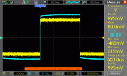
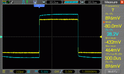
Based on suggestions from bonfis, I increased the values of the base stopper resistors and decreased the gain.
R23a & b 22R -> 68R (base stoppers)
R9 390R-> 1.5K (to reduce gain)
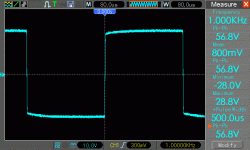
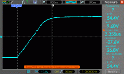
This seems to have fixed my oscillations problems. Below are the results into a 4ohm resistive load using a 30-0-30 300 VA transformer (the only one I have handy at the moment) as well as the revised schematic/layout reflecting the changes.
Could I use a 60-0-60 transformer with this amp if I have 100V+ rated capacitors?
If your previous post is correct, then you changed the wrong component.With 22r, I and others observed oscillations in the positive swing of the output. Increasing this stopped the oscillations.
Increased feedback requires new compensation values. increasing the base stoppers was hiding the problem. You should redo the compensation to suit the lower gain amplifier. This applies to all amps that were stable with a compensation to suit that gain. Reduce the gain and must change the compensation to suit.
Sorry Ranchu...... old charlie use to change names
real thing is capacitors.
Critical ones are input capacitor and the VAS compensation capacitor..the one we have discussed, values of 82pf pointed as safe.... there we use to install, when possible, Silver Mica capacitors, because more stable units...they are used in Radio Frequency transmitters, in the sites we have strong variation of signal, high curent, high amplitude and high voltage..they seem to be more stable...but for other positions... any dieletric material you find will fit without problems.
The ones you have in parallel with the electrolitic capacitors...that i call electrolitic condensers (Brazil call this way).... these ones are not critical.... respect the voltage only...but the dieletric material can be the one you found, the one you have, the one you like, the one has the size, the shape and the colour you want..... and value not critical...can go from 10N to 2.2uf....and you can have different values also...you can put one 10N, other 22n, other 22N, other 47n...no problems...they are there just to provide a low impedance patch to drain high frequencies to ground...because electrolitic capacitors are not that good to drain these currents to ground.
Another critical one is the bootstrapp one.... the one in between two 470 ohms resistors... feeding the NPN driver and also the VBE multiplier (stand by current adjustment transistor and also heat sensor).... but it is critical about voltage insulation...there, i suggest you to install an unit that can face rail to rail voltage.
The real thing in this life is that if you believe polipropilene or something alike Teflon...or other material as dieletric, can make some magic..then you should use...because you will "perceive" and "feel" the illusion matching your belief...... i mean...if you believe..then you gonna listen it as good.
Sounds strange to you?.... but this is psychology..... if you believe your wife is the best wife in this world (non sense because you had not lived with all wifes of this world..so..cannot say that...have not the knowledge)..then you will perceive her this way..you gonna be happy and gonna be living with that lovely illusion...even if your wife is the worst and ugly alike a crash of a bus against a wall...but having the belief you will be happy with your illusion....so.. .. do what you believe.
regards,
Carlos
Last edited:
If your previous post is correct, then you changed the wrong component.
Increased feedback requires new compensation values. increasing the base stoppers was hiding the problem. You should redo the compensation to suit the lower gain amplifier. This applies to all amps that were stable with a compensation to suit that gain. Reduce the gain and must change the compensation to suit.
I thought the reason for base 'stopper' resistors is to 'stop' oscillations
If all compensation is around main gain stage only, then I'm confused.
All transistors in the amp can oscillate, so why not use higher base stoppers.
As for reducing gain, a gain of 60ish should be easy enough to obtain.
But if you using a preamp then reduced gain in power amp is ok.
Regards
1kHz square wave into 4R
Here's a scope trace of 1kHz signal into my build (schematic from
http://www.diyaudio.com/forums/soli...mkiii-hx-builders-thread-176.html#post3581806)
Here's a scope trace of 1kHz signal into my build (schematic from
http://www.diyaudio.com/forums/soli...mkiii-hx-builders-thread-176.html#post3581806)
Attachments
If your previous post is correct, then you changed the wrong component.
Increased feedback requires new compensation values. increasing the base stoppers was hiding the problem. You should redo the compensation to suit the lower gain amplifier. This applies to all amps that were stable with a compensation to suit that gain. Reduce the gain and must change the compensation to suit.
Just to be clear the instability was encountered in my amp before any change was made to the amplifiers gain. After the oscillation was tamed by increasing the stoppers I made the changes to reduce the gain. At that time I also reduced Cdom to 100 pf and have seen no stability issues. Are you suggesting that the compensation of the original design at the original gain was incorrect and created the oscillation problem? I have no evidence to offer on that given the order of the changes I made.
Here's a scope trace of 1kHz signal into my build (schematic from
http://www.diyaudio.com/forums/soli...mkiii-hx-builders-thread-176.html#post3581806)
Thats a lot of tilt , have you done the mods suggested...?
Last edited:
Awfull unstability dear Radioflash
Amplify the image.... see the horizontal positive trace...it looks you have oscilation there (or uncle charlie became blind)...low level oscillation... triggered one!...this is a hell hard to fix....wonderfull! .. i love when this happens at home....I would love to see that in my home amplifier...this is a real fun to fix...but i have not here.
I suggest you to pick a capacitor, start with small value....let's say 220pf... glue it into a plastic pen case...one side must have a flexible wire connected to ground (main ground, not the lifted one.... then you try the lifted one).... then, holding the capacitor with the pen (do not touch the capacitor ceramic body), goes touching the sensitive parts of your circuit...differential, and VAS.
Well...if you do not already have made it..... this is basic sniffing of troubles...it is delicious...i would love to have this trouble here...it is pure fun to be tracking!
Awfull waveform!.... and lovely as we can fix it!.... this smells couterfeit transistor in place.... they sometimes pick lower power RF units and change the name of it.... a hell oscilating devices they sell as high power transistors...re marked... a cheaper one with code number of a expensive top of the line device.... people will run to buy.... top transistors and cheap!
Not oscillating?.... then give a shot on that scope.... hold the double barreled 12 gauge with a big slug on it...point to the center of the screen.... switch your camera to record and give a shot to blow out this piece of.... piece of..... piece of damaged electronics
regards,
Carlos
Last edited:
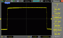
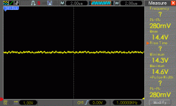
Attached are zoomed in view of a 1kHz square wave into 4R. The first snapshot is at full range (10 v/div, 40us/div). The second is zoomed into the top of the square wave and is 1v/div, 2us/div.
Is this indicative of RF noise/oscillations, or artifacts from my scope?
Is this indicative of RF noise/oscillations, or artifacts from my scope?
Attachments
Attached are zoomed in view of a 1kHz square wave into 4R. The first snapshot is at full range (10 v/div, 40us/div). The second is zoomed into the top of the square wave and is 1v/div, 2us/div.
Is this indicative of RF noise/oscillations, or artifacts from my scope?
What is your signal source? I have seen similar looking waveforms from sound card based generators. Do you have an analogue generator/oscillator?
My scope is a Hantek DSO5102B and my signal source is one of those cheap signal generators from eBay, model UDB1202S.
Hi radioFlash-
Your trace artifacts look very random to my eye not like oscillation more like noise. By comparison the screen shots in your post 1745 show a regular pattern on the sine wave peaks that looks very much like what I observed on my scope prior to changing the stoppers (see post 1241). My scope is an analog Tektronic and the signal source was an analog HP generator.
Radioflash were you able to determine if your issue was noise...
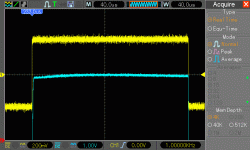
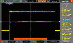
I believe it was just noise. When I switch the scope to average mode and zoom in, I don't see signs of oscillations.
Attached are traces of 1 khz square wave at full scale and zoomed in without averaging and with averaging turned on.
I've been playing music with with it and and am very happy with the performance.
Attachments
Run a wire from your ground and attach it into the heatsink
Watch the scope again.....maybe..... a good try.
In the reality.....we bother ourselves with small thngs that usually does not sound...... but this one sounds...it results harshing in the high end treble, this use to modify a little the timbre (what allow us to identify the instrument is playing)....some guys will love this effect, and they will not understand the stuff as a defect..they will understand as an effect.
Some guys spend hours trying to reproduce this stuff because the high end results..... people try to unstabilize...can you believe?...and we trying to stabilize....funny stuff.
So, if it is sounding good to you....do not bother yourself..let it be.... a hell with the scope and waveform...this thing must be good to you.
regards,
Carlos
Last edited:
- Status
- Not open for further replies.
- Home
- Amplifiers
- Solid State
- Dx Blame MKIII-Hx - Builder's thread
