Thanks for your reply Andrew. About the ripple, I don't worry too much as I don't seem to be able to get a flat line with my scope. Maybe I don't use properly or there's some interference screwing its trace. Even when input in GND'ed the "flat" line is rippled.
When I change the MJE15032 VAS, do I need to change the MJE15033 CCS as well??
Do you have any suggestion that I could use instead?
EDIT: Found a list: http://users.tpg.com.au/gerskine/greg/vas transistors.htm
Regards,
Martin.
When I change the MJE15032 VAS, do I need to change the MJE15033 CCS as well??
Do you have any suggestion that I could use instead?
EDIT: Found a list: http://users.tpg.com.au/gerskine/greg/vas transistors.htm
Regards,
Martin.
Last edited:
The ripple is almost certainly rail ripple due to the very high current passing through the amplifier when it clips into the test load.
I suspect that if you increased the load resistance you would find that the clipping ripple will decrease and when you clip into a 10k load the ripple will be gone.that might be rail ripple coming straight through the wide open output stage.
I have the same problem, finding nice VAS transistors,
Some I've used
http://www.datasheetcatalog.org/datasheet/sanyo/ds_pdf_e/2SC3788.pdf
and
http://www.cordellaudio.com/book/datasheets/KSC3503.pdf
I have used MJE 340/350 but they not the best for this function.
Always check for pins compatibility.
Change CCS also.
Regards
Some I've used
http://www.datasheetcatalog.org/datasheet/sanyo/ds_pdf_e/2SC3788.pdf
and
http://www.cordellaudio.com/book/datasheets/KSC3503.pdf
I have used MJE 340/350 but they not the best for this function.
Always check for pins compatibility.
Change CCS also.
Regards
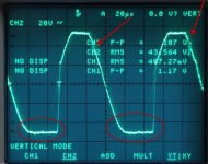
Well, I returned to simulation and guess what?!? The problem is there also, it's less obvious than in real life but it's there.
In fact two problems are shown... the sticky negetive rail and a kind of glitch on the positive side when starting to go down.
I've implemented the clamping diode as suggested by Vostro in simulation and it definitely solves the sticky rail. Gotta wait until I get the real ones now.
Anyone has a clue concerning the dent on the downward cycle?
Images:
Attachments
After you get hold of the diode, and install it.
I think that would stop the amplifier from "crazy oscillation".
The slight ringing will still be there, but should not take over and cause oscillation.
My suggestion is to be satisfied with that outcome, but only if it can go into and out of severe clipping without loosing stability while loaded and unloaded at all reasonable frequencies.
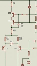
If you not satisfied, then try to add C9 as in my drawing,
I think the ringing comes from the LTP when coming out of saturation.
This capacitor should not affect high frequency distortion negatively, but you might have to tweek the value, I would use 1nF as starting point.
I don't think this will be a popular mod, and I don't know if it will work, I've never tried it.
Regards
I think that would stop the amplifier from "crazy oscillation".
The slight ringing will still be there, but should not take over and cause oscillation.
My suggestion is to be satisfied with that outcome, but only if it can go into and out of severe clipping without loosing stability while loaded and unloaded at all reasonable frequencies.
If you not satisfied, then try to add C9 as in my drawing,
I think the ringing comes from the LTP when coming out of saturation.
This capacitor should not affect high frequency distortion negatively, but you might have to tweek the value, I would use 1nF as starting point.
I don't think this will be a popular mod, and I don't know if it will work, I've never tried it.
Regards
Attachments
My suggestion is to be satisfied with that outcome, but only if it can go into and out of severe clipping without loosing stability while loaded and unloaded at all reasonable frequencies.
... you demonstrates wisdom, it's a good suggestion
") Will try the cap in simulation as well...
Will try the cap in simulation as well...Thanks!
Put it to play loud with these songs provided in the attached video
There are free software available to extract the MP3 from Youtube's video...but i can provide you if you write to me, i have the master here.
Well..there's no more master in digital media..all the same..all master.
These songs have no copyrigth....sound is interesting..not awesome but has different instruments, some high frequencies, some drums, hit hats and all we need to "feel" an amplifier.
Girls in the video are my daugthers.
Maybe you gonna like it:
Dx Corporation pictures - YouTube
regards,
Carlos
Well, I returned to simulation and guess what?!? The problem is there also, it's less obvious than in real life but it's there.
In fact two problems are shown... the sticky negetive rail and a kind of glitch on the positive side when starting to go down.
I've implemented the clamping diode as suggested by Vostro in simulation and it definitely solves the sticky rail. Gotta wait until I get the real ones now.
Anyone has a clue concerning the dent on the downward cycle?
Images:
Hi Mart
I took a look back at my post 1294 that shows my amp at clipping. I have a much less severe degree of rail sticking and a smaller glitch on the negative going slope just after the positive clip. Our amps differ in the value of the stopper resistors 56 vs 100 ohms and mine has been modified for lower gain. I don't know if this suggests any clues about dealing with your situation but thought it was worth noting.
Steve
Thanks Steve,
I didn't get my clamping diode yet so I don't have anything new. Got to mention that I also decreased Cdom to 100pF, but in simulation the value of that cap doesn't seems to modify the resulting trace at all.
As soon as it clips, the headroom I have from clipping to rail sticking to oscillations is very very thin. The amp doesn't cope well with clipping situation, I can't consider it "healthy". Expectedly the clamping diode will permit going into and out of clipping without any problem.
As far as the musical experience is concerned, I don't drive that amp into clipping. Real-world listening is not impaired by its unhealthy clipping behavior. Up to clipping, the scope trace is nice and smooth... and the amp sounds good
Will post more when Cdom is clamped.
Mart.
Look at his scope traces, sticking is visible. Stop-resistor value changes nothing on sticking at the bottom or "denting" the downward slope at clipping in the simulator. Stop-resistor only prevents the positive-side ringing.
Martin.
Martin is correct. I have sticking although it looks less dramatic than his. I accept that this probably has little to do with the stopper resistors. My version has other differences from the original MK III including a larger feedback factor and different input stage degeneration resistors. I don't know if these differences are likely to be relevant to the current problem. Perhaps one of our more technically astute thread watchers could weigh in on that issue.
Steve
Success
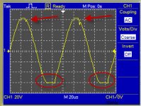
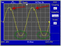
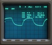
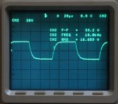
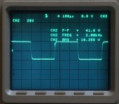
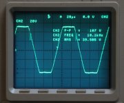
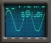
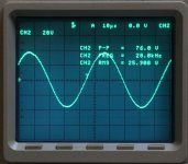
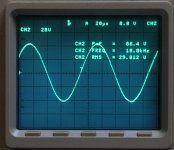
As suggested by Vostro, I've clamped the Miller cap and now rail sticking is gone. Here are some scope traces that shows some nice curves under normal conditions as well as during clipping and hard clipping.
Frequency and amplitudes are shown on the graphs. Don't worry about the ripples visible on the traces, I think I have a parasitic problem into the scope...
For thse who doesn't like the square waves, note that these tests have been made at 40v p-p.
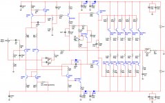
Even under hard clipping, never the amp has gone into oscillations, so that's good. I also join the exact schematic of the amp tested. The load was a 6r/300W resistor. The bias was set at 16mV between two output resistors.
BTW, I burned my speaker protection relay, under heavy clipping at 20KHz, the speaker-prot has triggered... and the contacts went into smoke (D'UH).
Enjoy!
As suggested by Vostro, I've clamped the Miller cap and now rail sticking is gone. Here are some scope traces that shows some nice curves under normal conditions as well as during clipping and hard clipping.
Frequency and amplitudes are shown on the graphs. Don't worry about the ripples visible on the traces, I think I have a parasitic problem into the scope...
For thse who doesn't like the square waves, note that these tests have been made at 40v p-p.
Even under hard clipping, never the amp has gone into oscillations, so that's good. I also join the exact schematic of the amp tested. The load was a 6r/300W resistor. The bias was set at 16mV between two output resistors.
BTW, I burned my speaker protection relay, under heavy clipping at 20KHz, the speaker-prot has triggered... and the contacts went into smoke (D'UH).
Enjoy!
Attachments
If you not satisfied, then try to add C9 as in my drawing
Hi Canonnica, if you dont mind would you try the 1nF capacitor too,
I'd like to know if it affects the positive slope behaviour,
Again, I'm not sure, but interested
.Regards
Vostro, I tried multiple values and it changed nothing in the simultator. sorry, I don't have any clue about it. A lot of search on forums and a lot of combinations in the simulator led me to nowhere... We'll have to understand by ourselves.
Maybe you're gonna discover what we'll one day call the "Vostro capacitor" or the like, eheheh.
Cheers.
Maybe you're gonna discover what we'll one day call the "Vostro capacitor" or the like, eheheh.
Cheers.
- Status
- Not open for further replies.
- Home
- Amplifiers
- Solid State
- Dx Blame MKIII-Hx - Builder's thread