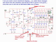
... back in the listening environment...
the high-bias setting of 54mV let the amp sound dull and kind of tarnished. Less engaging, less crisp. As expected and mentionned everywhere on this forum, adjusting the bias is like putting salt on a soup. Some will like it with more, some with less. I've made some listening tests at 16mV and 24mV. For now, it's set at 16mV and I'm quite satisfied by the balance.
The 100 Ohms base-stopping has permitted going upper than, let's say 12mV (it was oscillating) so to try and listen to it. My mods are there to stay. 16mV also has the advantage not to transform the amp into a room heater.
Juan, about your boards. Personnally, I would work in the opposite direction you actually do. The boards were already quite big. Making them bigger will make builder's life even more complicated. And I'm not sure you solve any real world issue we faced; not enough space for some electrolytics, holes too small for many components (ex: diodes), cooling for VAS and its CCS, a missing capacitor on the schematic, etc...
Why don't you try to create a board with no reservoir caps and only 3 output pairs and plan to only use 54-56VDC input and rate it at 150W into 8 ohms? This would be more than enough for the majority and ease it's adoption. (these are my 2¢ only, you'Re the boss") )
)
Martin.
the high-bias setting of 54mV let the amp sound dull and kind of tarnished. Less engaging, less crisp. As expected and mentionned everywhere on this forum, adjusting the bias is like putting salt on a soup. Some will like it with more, some with less. I've made some listening tests at 16mV and 24mV. For now, it's set at 16mV and I'm quite satisfied by the balance.
The 100 Ohms base-stopping has permitted going upper than, let's say 12mV (it was oscillating) so to try and listen to it. My mods are there to stay. 16mV also has the advantage not to transform the amp into a room heater.
Juan, about your boards. Personnally, I would work in the opposite direction you actually do. The boards were already quite big. Making them bigger will make builder's life even more complicated. And I'm not sure you solve any real world issue we faced; not enough space for some electrolytics, holes too small for many components (ex: diodes), cooling for VAS and its CCS, a missing capacitor on the schematic, etc...
Why don't you try to create a board with no reservoir caps and only 3 output pairs and plan to only use 54-56VDC input and rate it at 150W into 8 ohms? This would be more than enough for the majority and ease it's adoption. (these are my 2¢ only, you'Re the boss
)Martin.
Sound quality is a matter or tweaking and tuning
Much more sweat, sensitivity than wisdom.
Some folks believe calculation is the solution...no way.
I am glad you are concluding this stuff doing...i feel good, as i am 8 years long repeating the stuff and some guys thinking i am crazy.
In a matter of monthes we gonna have hundreds thinking the same way...because it is a real knowledge..tunning, calibrating, adjusting.
You will see that some errors contribute to some result.... make some big mistake..for instance..install positive rail a big resistor...much bigger than the negative and watch the harmonics.... wanna tube alike sound..then mess with the amplifier, because tube performance (at simulators and instruments) are awfull.
regards,
Carlos
About your suggestion Cannonica..about smaller board
with three output pairs..this will drive the boss to become mad because the Corporation phylosophy not to make two amplifier almost the same...unless too much needed.
Doing this way he will go to the past.... an advance to the past.... a step ahead backward?
Please, spend a couple of minutes and watch this project here....the Supercharged is almost the same if Juan produces the smaller board you have suggested:
DX Blame Amplifiers - Carlos Mergulhão
I do think uncle charlie will dress the "boss clothing " and will start to bite Juan in the rear back bumper.
ahahahahah!
regards,
Carlos
Attachments

Last edited:
Yeah I almost made a mistake to redone something that was already good enough I rather leave it like that is ok connonica and Carlos it think is better leave it that the board was made from meanman64 group buy many people have it including myself and satisfied with the sound I'm not an expert but I'm just happy that I build it also MKII Supercharged is more than enough maybe later but is just not necessary.
Regards
Juan
Regards
Juan
So best for you is base stoppers at 56 ohm and bias at 16mv ..?
I went with 100 Ohms. Tweak you own and make it sound like you want it to sound to...
Hot news
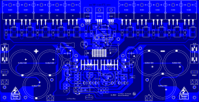
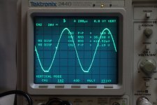
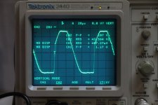
I found a used 'scope and started measuring things.
I used an iPhone app as a signal generator, surprizingly it's quite good.
I used a resistive load of 6 Ohms for all the tests.
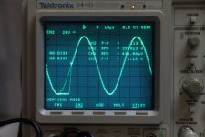
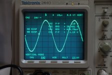
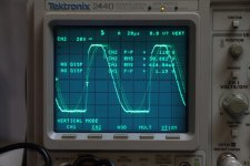
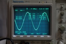
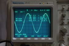
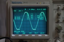
Here's some traces... we can observe some negative rail sticking when pushed beyond clipping, but up to there, it's just sweet.
ENJOY!!
This is for channel A
I found a used 'scope and started measuring things.
I used an iPhone app as a signal generator, surprizingly it's quite good.
I used a resistive load of 6 Ohms for all the tests.
Here's some traces... we can observe some negative rail sticking when pushed beyond clipping, but up to there, it's just sweet.
ENJOY!!
This is for channel A
Attachments
-
 ChanA-20KHZ_beyond_clip_6R-load.JPG383.3 KB · Views: 48
 -
 ChanA-20KHZ_at_clip_6R-load.JPG384.9 KB · Views: 66
 -
 ChanA-10KHZ_beyond_clip_6R-load.JPG384.5 KB · Views: 57
 -
 ChanA-10KHZ_at_clip_6R-load.JPG381.2 KB · Views: 235
 -
 ChanA-1KHZ_beyond_clip_6R-load.JPG381.3 KB · Views: 254
 -
 ChanA-1KHZ_at_clip_6R-load.JPG383 KB · Views: 277
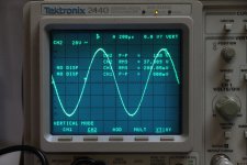
And channel B...
Attachments
-
 ChanB-20KHZ_beyond_clip_6R-load.JPG383.8 KB · Views: 46
 -
 ChanB-20KHZ_at_clip_6R-load.JPG382.5 KB · Views: 44
 -
 ChanB-10KHZ_beyond_clip_6R-load.JPG381.7 KB · Views: 38
 -
 ChanB-10KHZ_at_clip_6R-load.JPG386.6 KB · Views: 38
 -
 ChanB-1KHZ_beyond_clip_6R-load.JPG385.8 KB · Views: 45
 -
 ChanB-1KHZ_at_clip_6R-load.JPG384.7 KB · Views: 62
But before going forward with a solution, how can I identify the real problem?
Right now I see 3 possibilities for this happening:
1- the input current-mirror gets saturated
2- the VAS is sticking
3- the EF output is sticking
what can I check to identify the source of that issue? The solution will probably become obvious once I know it...
Martin.
Right now I see 3 possibilities for this happening:
1- the input current-mirror gets saturated
2- the VAS is sticking
3- the EF output is sticking
what can I check to identify the source of that issue? The solution will probably become obvious once I know it...
Martin.
Non symetrical clipping produces nice results.
But if you want to fix it, to put it symetrical, then will loose some advantages you had.
Check it in your simulator and then decide what to do.
I am busy doing other things...this amplifier and any amplifier will clip.... some will clip first the positive rail, others the negative rail, others will clip both same time (aproximatelly same time).... you will continue to have clipping anyway..but if this bothers you..then remove the clipping.
The way i suggest, or just reduce your volume knob not to enter clipping...you know, in photography we go one or two steps down to avoid saturation (F Stops)...but always you will have a spot with saturation anyway...if counter the ligth, against the light.
I am not angry, not mad, not snobing your work...i really like it...but will like more if this does not deviate me from other newer projects.
This kind of clipping produces soooooooooooooo! nice results ...you will realise this soon.
Like everything in this life needs compromise....maybe some guy will perceive his wife is getting fat and he may say:
- Honey, you are getting fat!..please, try a diet sweety
Then sweet wife looses weight...and became thin..and the breast reduce a lot..then husband may say.
- Honey, please, stop the diet and get fat back again!
regards,
Carlos
Attachments
Last edited:
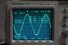
Well, I don't mind right now about the asymetrical clipping, I worry more about the rail sticking.
When I observe sticking, If I go just 1 or 2 volts higher in the output, the amp starts to oscillate like mad and in a matter of a few milliseconds, the speaker protection engages, which returns the amp in a stable state because no more load is applied.
If I continue cranking with no load, I blow fuses because it goes crazy into oscillation.
Vostro has the best solution as of now. I cannot find any of the suggested diode locally, I ordered some that will arrive next week.
In the meantime, if anyone have another hypothesis, it's welcomed.
very definitely the correct priority.Well, I don't mind right now about the asymetrical clipping, I worry more about the rail sticking.
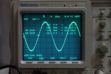
Rail sticking is not nice, some of your pics are showing severe rail sticking.
And yes find why it oscillates. That is an indication that something is not right in a big way. there may be some ringing in there that gives a clue to what is going wrong. Can I seeing a ripple where the amp comes out of clip? I do see ripple in the clipped wave, but that might be rail ripple coming straight through the wide open output stage.
What about changing that MJE15032 in the VAS. It's far too slow and far too high capacitance for this duty.
Don't worry about small differences in clipping symmetry, it might be due to slight differences in rail voltage, either at the front end, or at the output stage end.
- Status
- Not open for further replies.
- Home
- Amplifiers
- Solid State
- Dx Blame MKIII-Hx - Builder's thread