Me too I have him too, why? he know he's stuff but it is to high level for me, instead of help he is just too complicated, things like electronics advance explanations that I don't understand not because my English as a second language, I do understand pretty well "plain English" if he do that to just troll on the forum please just change your mind and help, I haven't see any project from him? do you have a PCB board made an audio amplifier schematic, or a power supply, or you just like to troll?
I would like you to explain that Cannonica
If he is feeding him i am too, and i do not want to be feeding people that i feel not positive.
Can you please explain.....maybe here is not the place to do that, but i feel very bothered with some guys we have in this forum and i would like to understand what you mean.
Please write to me and explain this "feeding him" please:
Do the best you can, please, Cannonica, and take into your account that i was 6 years into the College studying Psychology, so, i have some understanding about people...not total, because what happens to ourself does not allow us to make a good analisis, say, precise analisis..someone outside the "game" can evaluate a little bit better.
nanabrother@hotmail.com
carlos.eugenio1951@yahoo.com
Me and Juan will feel happy to know how we feed these small group of guys...as we do not want to do that.
I do think you are wrong...but there's always a possible mistake as i can be wrong instead of you..so..i can be making mistakes.... where there's no light we cannot feed light... a logical impossibility...it is alike a father that has a bad educated son... that father cannot educate his son because he is not educated..so... this is not logic.... people cannot give what they do not have..how offer something you have not?... if there's no ligth how to give clarity?... i cannot feed darkness as i have not a dark or evil mind and soul....i cannot give darkness or feed this stuff as i have not this in my heart and sould to give.
Well...go to my email if you really want to help
regards,
Carlos
Last edited:
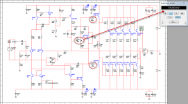
Because the miller compensation circuit includes two transistors, is there a risk of increased local instability?
Would it be beneficial to include a second capacitor as a feed-forward path which would bypass the emitter-follower at high-frequencies??
See pic.
Would it be beneficial to include a second capacitor as a feed-forward path which would bypass the emitter-follower at high-frequencies??
See pic.
Attachments
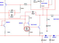
Miller compensation over the main gain stage, in this case enclosing 2 transistors is usually sufficient, Im not sure if adding a capacitor over b/e junction therefore increasing effective input capacitance would offer more pros than cons
Maybe adding a even smaller capacitor to form lag compensation, would be more beneficial
Maybe adding a even smaller capacitor to form lag compensation, would be more beneficial
Last edited:
I have tried almost all options into this VAS
all kind of modifications were done.... and all them while listening.... doing comparison with another channel non modified (did it at the Blame ST)... and i found this one we are using the best option.. i am sure i have tried almost all possibilities...also current was changed up and down...also zener used, more resistors, less capacitors and more capacitors, higher values and lower values...other transistors, other kind of coupling.
Well....this is my expertise..to tweak the stuff.... the circuit is the final work...the best i could do it.
I have made a new schematic posted...it looks better into simulator, it looks different..but i doubt some people may perceive differences...only more "tuned" guys will notice, because the result i call as fat tone and thin tone....you can notice when there are harmonics that makes tones "fat"... the timbre goes strange.... applauses looks rain drops in metal ceiling.... air bubbles bowing when the ocean waves breaks and touches the sand sounds strange alike the sound of frying eggs...well.... it is not that easy to notice small changes in harmonic distribution.
I do think less than 50 percent of our people will notice these details...modern music are so loud, so compressed, so distorted that details my be hidden in the background..... but if you can perceive a stradivarius violine is playing ...then you gonna get it.
I would like you guys to try your ideas...put them into work..solder the parts you believe may make a difference and bring the result for us...this will help me a lot....do not forget to keep one channel standard to compare..and install separate volume knobs to adjust both channels at same power level....make your input mono installing a capacitor joining both channels together and bring to us your thoughs...do not go imagining....do it!
"tuned" means to me what some guys call "golden ears"....yes...these guys exist....there are folks that are more focused, they set their attention into details...these folks never knows what the singer is singing...they cannot even repeat words from the song...but they know each tone... they perceive saturation, distortion, harmonics , deepness, focus, clarity and realism...when others cannot do that, because they have not trained themselves to listen in a such way some few guys can.
If you work into a television broadcasting station you learn to observe these details..you never watch a program, or a movie in the same way others do...you are watching video levels, chrome level and chrome phase, image stability, black level and image transitions...audio level and audio equalization..... if someone ask the guy about what movie was playing he cannot say....but he can say it was darn redish.... the audio was too much compressed and there's some lack of bass.
regards,
Carlos
Last edited:
Hi Carlos,
I understand good, that you listened to the original mono channel amplifier, and to tweak the other mono channel amplifier?
I think you "should" always go listen to a stereo amplifier, to realy assess the differences in the amplifiers better.
Then you get an overall picture what the differences are.
My 2 cents.
I not attack your listening skills, understand me good")
Regards,
Rudy
I understand good, that you listened to the original mono channel amplifier, and to tweak the other mono channel amplifier?
I think you "should" always go listen to a stereo amplifier, to realy assess the differences in the amplifiers better.
Then you get an overall picture what the differences are.
My 2 cents.
I not attack your listening skills, understand me good
Regards,
Rudy
I'm still working in the simulator and I should admit that there's very little to tweak more. I have generated tons of fourrier and distortion analysis. That amp is tweaked to the bones. The only component alteration that improves things is to put the 56R driver base resistor instead of the actual 22R. This improves significanty the distortion level and the "simulated" stability, in particular in a low-bias setting. With the 22R (and low-bias) the simulator shows ringing in the positive side of the sinus wave. The 56R resistor completely erradicates this ringing and completely confirms Bonfis real-life experiment.
Going beyond 56R shows a slight degradation of the THD performance, in simulator 56R is the ideal value.
Of course biasing to have 27mV at each output resistor also get rid of the ringing and clearly improve the distortion.
I'm almost complete convincing me that the only modification I need to do is replacing "that" resistor.
That's a great amp Carlos
Last edited:
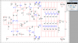
That's what i'm using since one year. I didn't open it since then. Along with simulation measurements.
Simulations made at full power (1.3VRMS input and 220W RMS at 8R load)
Simulations made at full power (1.3VRMS input and 220W RMS at 8R load)
Attachments
Last edited:
Here are the changes I want to implement.
The 56R resistor solely reduces the positive sinus wave ringing present in the sumultaor and confirmed by Bonfis. It does not alter the THD significantly.
The increase in quiescent current greatly reduces THD. The value across the two 0.47R resistors of 54mV is right on with the predicted value of Dr. Self for the lowest distortion level obtainable.
Simulations made at full power (1.3VRMS input and 220W RMS at 8R load)
Attachments
Last edited:
As a supplemental reading: http://www.sg-acoustics.ch/analogue_audio/power_amplifiers/pdf/audio_power_amp_design_comments.pdf
Here is an interresting thread on odd and even harmonics to sum up the sonics experience provided by them. It's probably referenced elsewhere on this board: Amplifier harmonics and load stability - Page 3
In defining what would be the best driver base stopping resistor and bias current, I realize that these two elements greatly affects the 2nd and 3rd harmonics balance. I'm now trying (in simulator) to determine what's the best theorical combination to erradicate the odd harmonic distortions while keeping some of the 2nd and other even harmonic ones.
When I'm done, I will implement the change and try to compare in the most objective way (which is not easy... )
In defining what would be the best driver base stopping resistor and bias current, I realize that these two elements greatly affects the 2nd and 3rd harmonics balance. I'm now trying (in simulator) to determine what's the best theorical combination to erradicate the odd harmonic distortions while keeping some of the 2nd and other even harmonic ones.
When I'm done, I will implement the change and try to compare in the most objective way (which is not easy...
)These days, I'm passing a lot of time in simulation. I try to evaluate the best combination vBias and driver base stop-resistor...
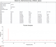
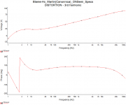
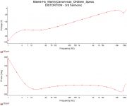
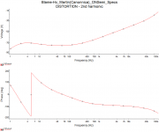
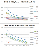
I'm exporting tons of fourier analysis into Excel spreadsheet to graph the results. Here is what I've found tonight...
These graphs represents the scenario where the resistor is of 56R in value and I only vary the vBias. The vBias is expressed in mV measured across both emitter resistors of output transistors.
The plot shows harmonics 2 through 9, their scale in on the left. The scale on the right is for the THD line (dark blue one).
I did these plots at a power of 100W RMS as at full power, the readings are scattered and they don't seem relevant. I will try other powers later on, it's very time consuming.
At 100W RMS, the 1st harmonic (reference output signal) has an amplitude of 40, the left axis shows the amplitude of other harmonics.
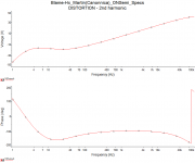
As I can see, the bias plays a very important role reducing the odd harmonics, which is logical as they're mainly due to crossover distortions. The even harmonics are not varying significantly, except for the 6th one that is quite high at low bias setting. I can't explain it now. I re-did the test several times with consistent results about that one...
I guess harshness is reduced as bias is increased and a warmer sound is expected... but i'm only into simulation right now.
Enjoy and comment!
I will do these plots for other resistor values and other powers as time permits
Martin
I'm exporting tons of fourier analysis into Excel spreadsheet to graph the results. Here is what I've found tonight...
These graphs represents the scenario where the resistor is of 56R in value and I only vary the vBias. The vBias is expressed in mV measured across both emitter resistors of output transistors.
The plot shows harmonics 2 through 9, their scale in on the left. The scale on the right is for the THD line (dark blue one).
I did these plots at a power of 100W RMS as at full power, the readings are scattered and they don't seem relevant. I will try other powers later on, it's very time consuming.
At 100W RMS, the 1st harmonic (reference output signal) has an amplitude of 40, the left axis shows the amplitude of other harmonics.
As I can see, the bias plays a very important role reducing the odd harmonics, which is logical as they're mainly due to crossover distortions. The even harmonics are not varying significantly, except for the 6th one that is quite high at low bias setting. I can't explain it now. I re-did the test several times with consistent results about that one...
I guess harshness is reduced as bias is increased and a warmer sound is expected... but i'm only into simulation right now.
Enjoy and comment!
I will do these plots for other resistor values and other powers as time permits
Martin
Attachments
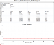
I don't follow.
I see % on the right hand vertical scale.
At the 0.1% level the harmonic for a 40Vpk signal (28.28Vac) should be 1/1000 or about 28mV.
The left scale shows values of voltage of 0.0003V (maybe 0.0002828), this is 0.3mV.
That to me seems to be a discrepancy factor of 100times.
I see % on the right hand vertical scale.
At the 0.1% level the harmonic for a 40Vpk signal (28.28Vac) should be 1/1000 or about 28mV.
The left scale shows values of voltage of 0.0003V (maybe 0.0002828), this is 0.3mV.
That to me seems to be a discrepancy factor of 100times.
- Status
- Not open for further replies.
- Home
- Amplifiers
- Solid State
- Dx Blame MKIII-Hx - Builder's thread