... you don't have any DC on the inputs ....
Are you sure?
")
It's to remove that uncertainty, DC is baaaad....
It's interresting to check the input caps and resistors...
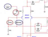
If I understand correctly, the components circled in RED serves as a high-pass, which in this case gives a f0 of 3Hz, and the ones in BLUE act as a low-pass in this case giving a f0 of... 3.29Mhz? Ain't that low pass rather high?
For that low-pass, can we change the value of the capacitor to something like 6.8nF, or increase the resistor value to 6.8K, or a a modification to both (resistor let's say 4.7K and cap to 330pF)? This would give a f0 of ~106-102Khz, which would be more suitable for that application.
Martin.
Attachments
Are you sure?
It's to remove that uncertainty, DC is baaaad....
Yes, but you would have to have really bad source to have DC and it won't be as bad as listening to that input. Cap...
It's interresting to check the input caps and resistors...
If I understand correctly, the components circled in RED serves as a high-pass, which in this case gives a f0 of 3Hz, and the ones in BLUE act as a low-pass in this case giving a f0 of... 3.29Mhz? Ain't that low pass rather high?
For that low-pass, can we change the value of the capacitor to something like 6.8nF, or increase the resistor value to 6.8K, or a a modification to both (resistor let's say 4.7K and cap to 330pF)? This would give a f0 of ~106-102Khz, which would be more suitable for that application.
Martin.
You may want to remove the output inductor if you are going for more bandwidth and speed ...
Junie, what pole is facing outwards, pos or neg?
Mart I did open my amp again
Negative connected to each other.
As I said, Carlos never designed any of the DX range of amplifiers to what amplifier designers would refer to as "normal" methods. He guessed and listened on whatever speakers he had to hand.Ain't that low pass rather high?
But he is not alone in this guessing and listening. There are other that do it. Eventually one stumbles upon a guess that works. Then the next stage is after a few amplifiers have been tweaked one recognises a pattern and starts to adopt that as an "empirical" design method.
Look at how many times, over the past 6 or 7 years, that the DX range has been modified and each version has been guaranteed by the designer to be the best sounding amplifier ever.
I would suggest you try a range of filter time constants to find the highest RC that lets you hear all the treble you need to hear. That range of RC time constants is likely to be from 330ns to 1.5us, but don't exclude the possibility that your preference lies outside that suggested range.
220r + 220pF gives RC ~= 48ns. I seriously doubt that was the highest RC that did not cut the treble.
Once you have found the low pass filter that works for you and your equipment it is likely that RC will suit all your power amplifiers. It may be worth then reviewing any other you have to see how big you can make your RC and still get all the treble you could ever want.
Last edited:
Mart I did open my amp again
Negative connected to each other.
Hahaha, sorry for that Junie
Thanks for your comments Andrew. Being in the process of learning, I think I started from the "empirical" side driving down to the more theorical and by-the-book side right now. Your technical comments help.
Mart.
Ok... I did some calculations and even simulations and here's my findings. I only worked on the low-pass thing.
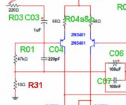
Refer to the image below for nomenclature.
With R3=220r and C4=220pF, the f0 is 3.3Mhz and RC is 48ns, which is somewhere on unknown roads (or is it know to be wrong roads?)...
Setting value of R3=2.7K and C4=470pF, f0 goes down to 125Khz and RC goes to 1.3us which would put us back on known pastures.
It will have an impact on the high-pass filtering as well because R3 and R1 are in series to the ground, but it will be somewhat negligible.
The sensitivity of the input will be decreased by about 5% (thus 5% less "global amplifier" gain).
Am I right with all of this?
And not the question that kills... why would one do this mod? ... Will it even alter the sound? Will it alter the stability of it?
Mart.
Attachments
Amps are quite sensitive to what appears at their inputs.
Interference for instance can be at VHF. It is usually better to attenuate that VHF interference before it gets into any amplifier.
Amps are also susceptible to misbehaving if the input is fed with very fast changing signals.
Filtering attenuates the very fast signals and thus gives the amp the chance to not misbehave.
For these reasons the low pass filter, that I believe should never be omitted, should be set as low as possible.
That "low as possible" must be compatible with good audio quality. Ideally it must not remove any audio information. Ideally it must not allow the amplifier to misbehave.
Getting both of those conditions satisfied is not easy. Hopefully the amp designer has got the misbehaviour part already sorted. Then it comes down to the user getting all the audio passing the filter as he/she requires.
By reducing overall gain, adjusting Fb for stability reduces the chance of VHF oscillations, getting rid of the dreaded inline cap will make for better sonics.
Granted with low resolution input signal and speakers , most may not hear the difference .
Capacitors are evil ..........
Granted with low resolution input signal and speakers , most may not hear the difference .
Capacitors are evil ..........
I jumped the input cap and....
I did some tests of bypassing the input cap with a jumper on my HX.
Note: My source has a DC offset of 0.3mV, which is nothing.
Soundwise; I didn't notice anything. Sound will change more if you just move your head. Lows, Mids, Highs are the same, i didn't notice any difference.
Technicalwise; With the input cap jumped, there's about -460mV offset at the speakers... woups, that's bad. That's enough to make my woofer recess a bit in its enclosure.
It is probably due to the -375mV bias voltage at the signal input of the differential pair. Watch-out for that voltage to leak into your source with cap removed/jumped!!
So I won't be seen jumping that cap.
Martin.
I will not agree to this all encompassing blanket statement............. impossible to believe that input cap does not have a "sound ", all caps add color .............
He reported what he heard.
He reported how he did it.
He reported the downside of unpredictable output offset.
I would much rather believe what he presents than believe you.
I would also never recommend DC coupling nor mixed AC & DC coupling without taking the other precautions that I believe become a necessity and have detailed in previous posts. That does not detract from Canon's post.
what evidence have you obtained to support this conclusion?Capacitors are evil ..........
Are you prepared to offer up that evidence?
Or do we just ignore your unsubstantiated comment/s?
Last edited:
the input filters are passive. They are also outside the feedback loops.Am I right with all of this?
The changing of the R3 to R1 ratio changes the sensitivity of the input. It does not change the amplifier gain.
Are you asking me to proved proof that capacitors "have a sound" ..
I'm also not denying his reported results , actually applaud the effort, just surprised by it , that's all ..
Now what about my question about GL issues ?
What about the increased DC offset any suggestions there, Martin did not state the value with no input, that may tell us something ..
I'm also not denying his reported results , actually applaud the effort, just surprised by it , that's all ..
Now what about my question about GL issues ?
What about the increased DC offset any suggestions there, Martin did not state the value with no input, that may tell us something ..
- Status
- Not open for further replies.
- Home
- Amplifiers
- Solid State
- Dx Blame MKIII-Hx - Builder's thread