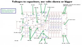
now i cannot find a 100V in a small package for the capacitor circled in red, can i use a 100uF/50v?
Hi Junie,
I hope this helps, drawing from Carlos.
I use 100volt caps.
Regards,
Rudy
Attachments
Last edited:
changing the lower NFB resistor from 390r to 2k2 changes the gain margin and phase margin of the closed loop amplifier.I've changed 390R resistance to a 2.2 K resistor.
The amplifier is bound to perform differently, before an after the feedback change.
BMW,
your test and reported conclusion are completely flawed.
Your description of the modification is correct and confirms you are listening to two different amplifiers that by design must perform differently.
That 100uF capacitor that is the DC block in the NFB path could be a 3Vdc component and the amplifier would still perform well.
If one wants to ensure that the low voltage cap in this blocking position is never abused then add a diode across it so that worst case DC voltage across it is <1Vdc.
You can also add an inverse diode across this same capacitor to protect it from voltage abuse (when something goes wrong) from the other polarity.
Some will report that higher voltage electrolytics perform better than lower voltage electrolytics when passing audio signals.
This DC blocking capacitor should have near zero DC voltage across it, when the amplifier is operating properly and should also have near zero AC voltage across it when the amplifier is operating properly.
A DC blocking capacitor that has no DC voltage and no AC voltage across it cannot contribute to the distortion that the amplifier creates.
i.e. A properly sized DC blocking capacitor cannot be heard.
Make it big and use low voltage if the space/cost requires that.
Use the input capacitors to limit the bandwidth of the amplifier.
Last edited:
Hi Space2000,
the voltage drop across a standard LED is about 2V.
To let the LED shine with say 5mA, you must calculate the value of a resistor across which 58V (since you are using a +/- 60 VDC PSU) will drop while 5mA is flowing.
Take a 10K resistor, connect the cathode of the LED to GND, the anode of the LED (the anode's leg is the longer one) to one side of the resistor and the other side of the resistor to your positive rail voltage.
Reverse the LED while connecting to the negative power rail.
Best regards - Rudi_Ratlos
Hi Space2000,
the voltage drop across a standard LED is about 2V.
To let the LED shine with say 5mA, you must calculate the value of a resistor across which 58V (since you are using a +/- 60 VDC PSU) will drop while 5mA is flowing.
Take a 10K resistor, connect the cathode of the LED to GND, the anode of the LED (the anode's leg is the longer one) to one side of the resistor and the other side of the resistor to your positive rail voltage.
Reverse the LED while connecting to the negative power rail.
Best regards - Rudi_Ratlos
Thanks for help.
That 100uF capacitor that is the DC block in the NFB path could be a 3Vdc component and the amplifier would still perform well.
If one wants to ensure that the low voltage cap in this blocking position is never abused then add a diode across it so that worst case DC voltage across it is <1Vdc.
You can also add an inverse diode across this same capacitor to protect it from voltage abuse (when something goes wrong) from the other polarity.
Some will report that higher voltage electrolytics perform better than lower voltage electrolytics when passing audio signals.
This DC blocking capacitor should have near zero DC voltage across it, when the amplifier is operating properly and should also have near zero AC voltage across it when the amplifier is operating properly.
A DC blocking capacitor that has no DC voltage and no AC voltage across it cannot contribute to the distortion that the amplifier creates.
i.e. A properly sized DC blocking capacitor cannot be heard.
Make it big and use low voltage if the space/cost requires that.
Use the input capacitors to limit the bandwidth of the amplifier.
Andrew, isn't it adding a diode in NFB will rectify the output signal which lead to DC presence in the input stage? Maybe i'm wrong
You're wrong.
The NFB DC blocking cap should never have any significant voltage across it, when the amp is operating properly.
If there is no voltage there is nothing to rectify.
If the amp develops a fault that creates a voltage across the DC blocking cap then the diode limits the cap voltage to <1Vdc. i.e. the cap cannot be damaged when the amplifier output stage blows up.
changing the lower NFB resistor from 390r to 2k2 changes the gain margin and phase margin of the closed loop amplifier.
The amplifier is bound to perform differently, before an after the feedback change.
BMW,
your test and reported conclusion are completely flawed.
Your description of the modification is correct and confirms you are listening to two different amplifiers that by design must perform differently.
Andrew, please tell me how I can do it otherwise, so I change the input sensitivity “390R to 2.2K” to the desired result with my preamp?
I am open for everything even for other suggestions, but please tell me what to do.
You tell me the test and reported conclusion are completely flawed.
That may be, but this amplifier sounds now to a level where I want to go maybe further, even though it is true no more how this amp is designed.
You says, I listen to two different amplifiers, which I can confirm because it sounds different , but as I said this is the level where I want to go.
I have listened a number of years ago to a UCD400 classd amp with a tube entrance, that sounded a lot better than the default UCD400.
I know this has nothing to do with this amp, but the design was also completely different.
Hopefully I become understood correctly, English is not my mother tongue.
Regards,
Rudy
take your original amplifier and replace the 390r with a 2k2.
now compare the original to the new.
are they the same or different.
measure the original and the new.
are they the same or different.
Now swap the 1% 600mW 2k2 metal film to your fancy and expensive 2k2
measure the two and compare.
are they the same or different.
Listen to the two versions.
are they the same or different.
This resistor creates an interresting lot of fuss... It has lead me to reconsider the value Carlos was suggesting in his schematics.
The suggested 390r value sets the amp to a gain of 121.5x, or near 42dB. This may be good for amplifying directly from a portable device like iPods, but when using a preamp, well, we need to turn down the input pot quite a lot.
My researches on the actual gain of many consumer power-amps shows that the typical gain for an amp of that power varies from 24x to 28x, which is between 27,6dB and 29dB.
Reducing the gain to a level of 28-29dB will raise considerably the signal-to-noise ratio and reduce the electrical noise pickup, which is all good obviously.
Reducing the gain is made by raising the amount of NFB which seems to work in the correct direction also to significantly lower the THD of the unit, AndrewT, is that correct? I still don't have all the knowledge about phase margin though.
So is it all good to increase the 390r resistor value to between 1.7K (28.6x or 29dB gain) and 2.2K (22.4x or 27dB gain) What are the gotchas???
Thanks,
Martin.
I am making Speaker protection circuit using DX protection circuit. i want to use 12v relay and my power supply is 12v DC.
Do i have to change some values?
http://www.nabucoeletronica.com.br/dx/files/spkprot-schematic.pdf
Thanks
Michael
Do i have to change some values?
http://www.nabucoeletronica.com.br/dx/files/spkprot-schematic.pdf
Thanks
Michael
This resistor creates an interresting lot of fuss... It has lead me to reconsider the value Carlos was suggesting in his schematics.
The suggested 390r value sets the amp to a gain of 121.5x, or near 42dB. This may be good for amplifying directly from a portable device like iPods, but when using a preamp, well, we need to turn down the input pot quite a lot.
My researches on the actual gain of many consumer power-amps shows that the typical gain for an amp of that power varies from 24x to 28x, which is between 27,6dB and 29dB.
Reducing the gain to a level of 28-29dB will raise considerably the signal-to-noise ratio and reduce the electrical noise pickup, which is all good obviously.
Reducing the gain is made by raising the amount of NFB which seems to work in the correct direction also to significantly lower the THD of the unit, AndrewT, is that correct? I still don't have all the knowledge about phase margin though.
So is it all good to increase the 390r resistor value to between 1.7K (28.6x or 29dB gain) and 2.2K (22.4x or 27dB gain) What are the gotchas???
Thanks,
Martin.
Martin here you have a point, this this is exactly where I had problems with my preamp.
I'm not yet started to test the 390R vs 2.2K resistance, hopefully next week.
Carlos has left this forum

Regards,
Rudy
Carlos is OK and happy
Here is his vlog and he is uploading videos almost every day: http://www.youtube.com/user/destroyersoueu?feature=mhee
Watch this he is telling is OK and something about the forum - http://www.youtube.com/watch?v=zMBux0kK8Zs&list=UU9xnp-350vDnDhEpNv_XVxg&index=2&feature=plcp
Regards!
Here is his vlog and he is uploading videos almost every day: http://www.youtube.com/user/destroyersoueu?feature=mhee
Watch this he is telling is OK and something about the forum - http://www.youtube.com/watch?v=zMBux0kK8Zs&list=UU9xnp-350vDnDhEpNv_XVxg&index=2&feature=plcp
Regards!
Last edited:
Glad to see that Carlos is fine and enjoying life!
I did some adjustments on my amp.
I wanted to get rid of the high-pitched hiss and the electrical hum when the amp is sitting idle.
So I lowered the gain grom 143x to 32x by replacing the 330 ohms resistor by an 1.5K (I went with a 330r instead of 390r initially... wrong direction one would say )
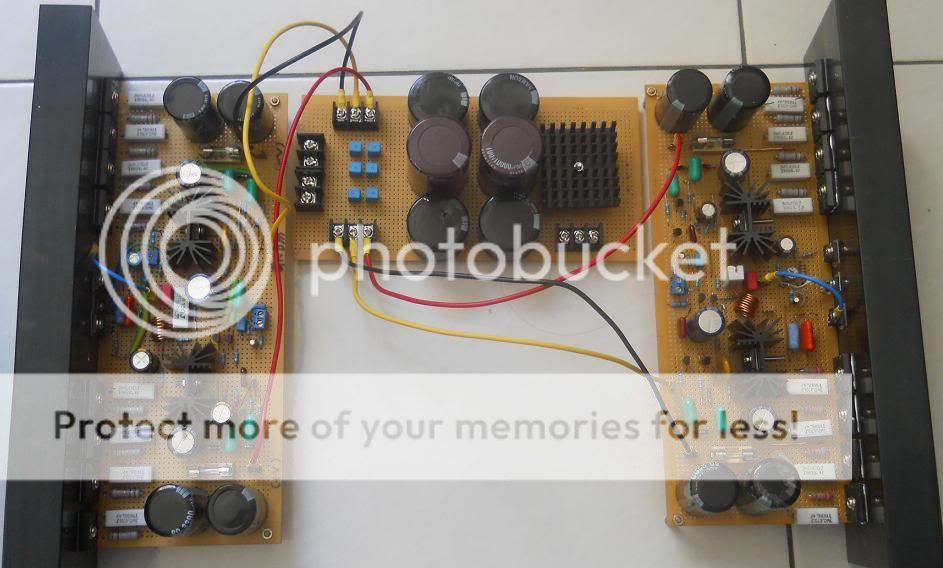
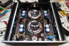
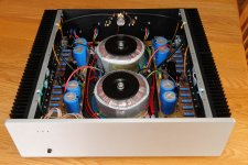
I also re-routed the power wiring over the main trannys using some custom brackets. Initially, those wires were running just below the signal inputs. (See the pics below)
So how's it now? Very silent and more satisfying. The high-pitched hiss is completely gone as well as the 60HZ buzz...
The sound has changed a bit too, I thought the amp was emphasing too much the high-mids, at the point of being harsh at higher volumes. This tendency is now gone and the frequency response seems more flat and natural.
Pics showing before and after the wiring rerouting:
I did some adjustments on my amp.
I wanted to get rid of the high-pitched hiss and the electrical hum when the amp is sitting idle.
So I lowered the gain grom 143x to 32x by replacing the 330 ohms resistor by an 1.5K (I went with a 330r instead of 390r initially
... wrong direction one would say )I also re-routed the power wiring over the main trannys using some custom brackets. Initially, those wires were running just below the signal inputs. (See the pics below)
So how's it now? Very silent
and more satisfying. The high-pitched hiss is completely gone as well as the 60HZ buzz... The sound has changed a bit too, I thought the amp was emphasing too much the high-mids, at the point of being harsh at higher volumes. This tendency is now gone and the frequency response seems more flat and natural.
Pics showing before and after the wiring rerouting:
Attachments
- Status
- Not open for further replies.
- Home
- Amplifiers
- Solid State
- Dx Blame MKIII-Hx - Builder's thread