No.
4700uF +4700uF connected in series = 2350uF
60Vdc is very close to the 63V maximum rating for the majority of affordable smoothing caps.
You may find that in worst case conditions that your mains supply takes your smoothing caps above 63Vdc. That will require you to specify 75V or 80V capacitors.
4700uF +4700uF connected in series = 2350uF
60Vdc is very close to the 63V maximum rating for the majority of affordable smoothing caps.
You may find that in worst case conditions that your mains supply takes your smoothing caps above 63Vdc. That will require you to specify 75V or 80V capacitors.
Can someone tell me how a speaker protection module works?
Works a speaker protection module only if the module gets voltage from the amplifier?
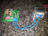
I hear no click after 10 seconds as it is connected, see picture 2
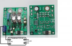
The small transformer is 1 x 12 volt.
Regards,
Rudy
Works a speaker protection module only if the module gets voltage from the amplifier?
I hear no click after 10 seconds as it is connected, see picture 2
The small transformer is 1 x 12 volt.
Regards,
Rudy
Attachments
Last edited:
Can someone tell me how a speaker protection module works?
Works a speaker protection module only if the module gets voltage from the amplifier?
I hear no click after 10 seconds as it is connected, see picture 2
The small transformer is 1 x 12 volt.
Regards,
Rudy
Hi,
According to the circuit diagram found here, that module connects between the amplifier output and the loudspeaker. When powered by a 12Vac supply, if a DC offset of positive or negative polarity is detected at the amplifier output, the relay contacts open and disconnect the load. There is also a delay of a few seconds before the relays close at power-up.
Regards,
currentflow
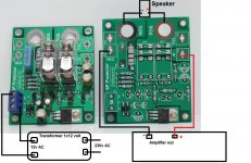
Another photo, this is the good way how the amplifier is connected to the module?
Regards,
Rudy
From your post #983, the 12V transformer is incorrectly wired. If you don't have a centre-tapped transformer, the transformer leads should go between "0" and one of the "AC" terminals. In this way, you will only achieve half-wave rectification of the 12V supply and this may be insufficient to power the circuit.
There has to be no voltage from the amplifier for the relays to connect the output to the speakers.
Last edited:
Kevin emailed me this:
Dear Sir:
http://www.okaphone.nl/product/images/212048c.jpg
This transformer is 12-0-12 full wave output.
What you need should be simpler one. Just need to have one 12-0 output, 1A current is quite enough.
Sincerely, Kevin
- vintage_audio_lab
Oke currentflow, I wire one to the 0 and the other to the AC.
Thanks
Last edited:
Kevin emailed me this:
Dear Sir:
http://www.okaphone.nl/product/images/212048c.jpg
This transformer is 12-0-12 full wave output.
What you need should be simpler one. Just need to have one 12-0 output, 1A current is quite enough.
Sincerely, Kevin
- vintage_audio_lab
Oke currentflow, I wire one to the 0 and the other to the AC.
Thanks
If you are using an external single-ended transformer in this circuit and not a 12V-0-12V type, you should verify that the on-board 12V regulator has sufficient input voltage to regulate correctly. Unless a low-dropout 12V regulator has been fitted, you will require at least 14.5V DC at the input to the regulator under load (i.e. relays activated) and measured between the junction of D1-D2 and GND. I don't envisage this will be a problem as you should be able to achieve approximately 16 VDC.
Last edited:
I measuring 13,2v between 0 and the entrance of the 7812 the current is to low.
I have the speaker protection tested with the light bulb tester and speaker protection works well.
Rudy
I don't think your transformer is adequate. What is its specification?
Can you measure the output from the regulator: a) with the relays on, and b) with the relays off please.
This isn,t the pcb that rudi sells I would read the instruction that came with this unit. Evette
There is no instruction manuel
")
I test the other speaker protection module and measure again.
Oeps, I measure with licht bulb tester.
Rudy
Last edited:
7812 regulator between 0 and out is 10.51 volt
Measuring 13,2v between 0 and the entrance of the 7812.
Rudy
You didn't say whether 10.51V was measured with the relays activated or not. Either way, the input voltage is too low for the regulator to operate correctly. The 7812 should produce 12 VDC (regulated) at its output and, while there may be just enough voltage to get the circuit working, it may prove to be unreliable. The absolute MINIMUM DC input to the regulator needs to be 14.5V.
Please advise me of the transformer specification, i.e. the quoted AC output voltage and its VA rating. Can you also measure the AC output voltage of the transformer when the relays are activated please.
Could you also confirm that the circuit at http://www.diyresearch.net/data/sp_protector_2ch/ matches your board. This is for a two-channel version, but should be similar to yours.
Regards,
currentflow
Last edited:
7812 regulator between 0 and out is 12.01 after click 10.51 volt
Measuring 18.05v between 0 and the entrance of the 7812 after click 13,2v
I connect the other transformer... after that I connect a 12v 10A I have here yet
Rudy
Measuring 18.05v between 0 and the entrance of the 7812 after click 13,2v
No it's not enough ...What you need should be simpler one. Just need to have one 12-0 output, 1A current is quite enough.
I connect the other transformer... after that I connect a 12v 10A I have here yet
Rudy
Last edited:
I'm surprised you're seeing such a voltage drop before the regulator when the relays activate. If the relays are type Omron G2R-1-E 12DC as shown on the BOM, they will be each consuming around 40 mA. The entire circuit shouldn't need more than 100mA and twice this for both audio channels. In other words, a 500mA transformer would be more than adequate, yet your 1A is struggling. Could your transformer be faulty?7812 regulator between 0 and out is 12.01 after click 10.51 volt
Measuring 18.05v between 0 and the entrance of the 7812 after click 13,2v
No it's not enough ...
I connect the other transformer... after that I connect a 12v 10A I have here yet
Rudy
Regards,
currentflow
First have the other 12v 1A transformer plugged and measure exactly the same.
Have just connected a 12v 10A transformer, and this measure the same.
What is the utility of this 7812 regulator in this circuit?
The speaker protector also works with the small transformer
Rudy
Edit: I send a email to vintage_audio_lab
Have just connected a 12v 10A transformer, and this measure the same.
What is the utility of this 7812 regulator in this circuit?
The speaker protector also works with the small transformer
Rudy
Edit: I send a email to vintage_audio_lab
Last edited:
Are the relays of the type I mentioned previously? Please confirm.First have the other 12v 1A transformer plugged and measure exactly the same.
Have just connected a 12v 10A transformer, and this measure the same.
What is the utility of this 7812 regulator in this circuit?
The speaker protector also works with the small transformer
Rudy
The purpose of the 7812 is to:
1) ensure that the relays operate at the right voltage &
2) ensure a consistent switch-on delay time.
As long as you don't exceed the maximum permissible relay coil voltage, you could remove the regulator and link the input to output pins.
However, a much better solution (assuming you don't have a 12-0-12V transformer) is to add two more diodes (type 1N4001-1N4007, or similar) to implement a full-wave bridge rectifier circuit. Then connect the transformer input between the two AC terminals. This will result in a greater voltage at the input to the 7812 under load and should solve the problem.
Yes I confirm this is Omron G2R-1-E 12VDC
2) The speaker protection module have a consistent switch-on delay time of 6 seconds.
I tested this module with 12v 10A transformer, and I have also a voltage drop ...
I hope the designer of the speaker protection module respond today on my email, he always respond.
I told him, I have a voltage drop, with this 7812 regulator.
I wait for his email, hope he respond on this forum he have the link.
Regards,
Rudy
The purpose of the 7812 is to:
1) ensure that the relays operate at the right voltage &
2) ensure a consistent switch-on delay time.
2) The speaker protection module have a consistent switch-on delay time of 6 seconds.
However, a much better solution (assuming you don't have a 12-0-12V transformer) is to add two more diodes (type 1N4001-1N4007, or similar) to implement a full-wave bridge rectifier circuit. Then connect the transformer input between the two AC terminals. This will result in a greater voltage at the input to the 7812 under load and should solve the problem.
I tested this module with 12v 10A transformer, and I have also a voltage drop ...
I hope the designer of the speaker protection module respond today on my email, he always respond.
I told him, I have a voltage drop, with this 7812 regulator.
I wait for his email, hope he respond on this forum he have the link.
Regards,
Rudy
Last edited:
Yes I confirm this is Omron G2R-1-E 12VDC
2) The speaker protection module have a consistent switch-on delay time of 6 seconds.
I tested this module with 12v 10A transformer, and I have also a voltage drop ...
I hope the designer of the speaker protection module respond today on my email, he always respond.
I told him, I have a voltage drop, with this 7812 regulator.
I wait for his email, hope he respond on this forum he have the link.
Regards,
Rudy
Thanks for your reply. I am fairly confident that adding two diodes will solve the problem. Fitting these is simplicity itself and can be done at the screw terminal block.
Connect one diode between the upper AC and 0 with the diode's band (cathode end) nearest the upper AC terminal.
Connect the second diode between the lower AC terminal and 0 with the band nearest the lower AC terminal. Connect your transformer between the two AC terminals only.
- Status
- Not open for further replies.
- Home
- Amplifiers
- Solid State
- Dx Blame MKIII-Hx - Builder's thread