heat sink
regards,
mj777
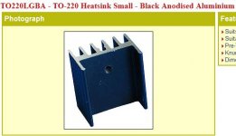
Please check this link maybe it will help,TO-220 Heatsinks, and there price are not that expensive, I have ordered online from them many times and the quality of the parts are also good.I already asked this question, but I'll try one more time.
I like the profile for the heatsinks for the MJE15030 and MJE15033 transistors Alex drew in the silkscreen, but can't find them. Does anyone know of such heatsink? If not, what is everyone using?
-Byron
regards,
mj777
Last edited:
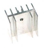
I found the perfect one
Thanks, everyone for the links. I found one exactly like what Alex drew on the silkscreen. It is at:
Heatsinks - TO-220 - TO220ST
Thanks, everyone for the links. I found one exactly like what Alex drew on the silkscreen. It is at:
Heatsinks - TO-220 - TO220ST
Attachments
Suppressors for switch noise are available.
I wonder if those are what you refer to?
The descriptions just said they're good for noise suppression. They didn't say what kind of noise. Here are several examples.
http://www.okaya.com/images/noise/1100.pdf
Vishay - Vishay's New X2 Interference Suppression Film Capacitors Feature Capacitance Values from 0.001 μF to 4.7 μF and Pitch Sizes Down to 7.5 mm
http://www.kemet.com/kemet/web/homepage/kechome.nsf/vapubfiles/KEM_F3011_PME271M_X2_275.pdf/$file/KEM_F3011_PME271M_X2_275.pdf
http://www.cde.com/catalogs/MPX.pdf
I found that they all had leads which were too far apart, so I went with normal caps.
I will disassemble my prototype to save parts
Was tested and worked great..no reason to keep prototype assembled when i need some parts are there not in use.
MKIII Hx prototype will be dismantled to save usefull parts - YouTube
regards,
Carlos
Was tested and worked great..no reason to keep prototype assembled when i need some parts are there not in use.
MKIII Hx prototype will be dismantled to save usefull parts - YouTube
regards,
Carlos
There's a trimpot A. Wayne, so you can adjust
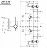
You can have 85 volts entering and adjust to any voltage you need...this gonna be a laboratory power supply, to feed several different power amplifiers as we can adjust output voltage.
The circuit shown, with Apex name on it, is the same i use that was a copy from Ampex Open Reel Video Tape recorders down the seventies..also used by Sony.... it is a generic series pass circuit that works very well...performance of this circuit is great and regulation can be within 5 percent.
Depending how many power transistors you have in the series pass, you can use it as main power supply and can use it as secondary power supply feeding VAS and first stage...in this last case you will not need a powerfull transformer and will not need high power series pass transistors.
Adjustable stabilized power supplies can be good as step down regulators, so you can have a 85 volts transformer and will need to power a 65 volts amplifier...then it will be a helping hand.
The trouble is that they must be as fast as your amplifier and better when the supply is faster than your power amplifier, say, correcting errors (voltage variations) very fast.
The main need, in my point of view is to use at least 20 plus 20 thousand microfarads in the output of the series pass, and hard is to do this way and continue to have a fast response of your error amplifier (that transistor and zener in the feedback patch)
A good circuit can help a lot your performance, will reduce modulations, will reduce distortions, will increase peak power compared with a non regulated supply (as voltage will stand still in the preset value)....but can destroy your amplifier performance if bad designed, bad adjusted, bad tuned to your specific current demand.
regards,
Carlos
Increases cost A Wayne..... the cost is almost the same you spend in your power
amplifiers.... current that will cross will be two channels current to a single regulator, there's some voltage drop over the series pass transistors and huge current.... this increases cost.
Also if you have a high power amplifier, draining several amperes, then you will need several output transistors and regulator input voltage use to be 20 to 30 volts higher than your output voltage.
Imagine a 60 volts power amplifier.... a regulator to it will have 80 to 90 volts... so, 20 to 30 volts higher than the output voltage.... and imagine the current....let's say 20 amperes each rail because two amplifier channels connected to the same electronic supply.... one rail will dissipate the voltage from the coletor to emitter multiplied by the current.... the voltage may drop to 75 volts loaded...so, 15 volts of voltage drop multiplied by 20 amperes results in 300 watts...and we are talking about one rail..... two rails will dissipate twice ..... now imagine the heatsink size to dissipate the heat resulted of 600 watts.
Not a good idea to use in high power amplifiers...this is good to 20 watts or 30 watts channel amplifiers, but even this way doubles the cost..so, the most rational way, the cheaper way, is to use a transformer, rectifiers and filters... to accept some voltage drop and save money.
To high power amplifiers it is a better idea to use a SMPS....but not a common, regular, generic, ordinary SMPS...it must use a very high frequency oscilator in order not to be amplified in your audio stages, say, captured as an interference and then amplified because the amplifier can do that (high frequency transistors)... this will overheat your amplifier if your SMPS is low frequency (20 to 40 Khz) with the signal being amplified...this will result in saturation, audio compression, losses of high end reproduction, compressed sound (no dinamics).
That SMPS (switching mode power supply) must be shielded inside a mu metal case (magnetic shield).
That SMPS must accept 30 thousand plus 30 thousand microfarads in it's output in order to have a very low impedance in the supply output seen by the amplifier...amplifier will "feel" a low impedance...the huge stock of electrons will be fast delivered to the load when the SMPS is not always fast enough to supply surge of currents to face transients or signal peaks...usually SMPS senses the surge of current when you switch the SMPS on and understand the surge as a short circuit and shut down the supply...so..... that supply must be a special SMPS, not a standard one..to accept huge bank of condensers in the output without enter the protection mode.
So, there are problems to use a SMPS, also there are problems to use a voltage regulator to high power amplifiers.... there are technical problems and huge costs too...weight, room inside the enclosure for big heatsinks (extra ones to the series pass regulator).
The most rational decision is to use the old and good transformer, rated to your power, a good and old bridge rectifier rated to your power and a huge bank of electrolytic condensers and not to complicate our life with all that stuff.
I am building because i need as a tool, to adjust the voltage need to supply energy to several different amplifiers and ideas i use to develop or test.... as a workbench instrument, a laboratory supply, adjustable, stabilized and huge....but i will never install that monster inside an enclosure to feed an amplifier.... when building an amplifier, inside the enclosure you will always see analog supply, conventional supply... trafo, rectifier and filters.
regards,
Carlos
Last edited:
Got my power supply up and running
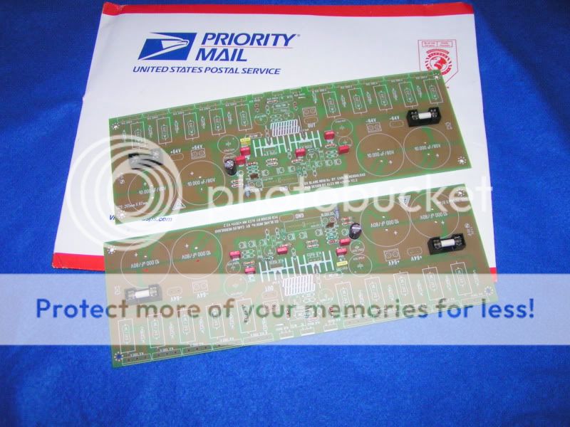
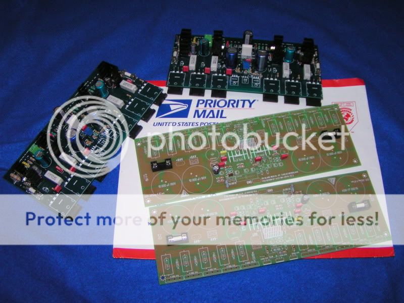
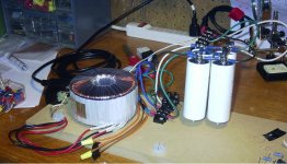
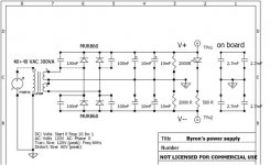
I'm posting a schematic & photo just because this is the first power supply I've designed and the second one I've built, so I'm feeling pretty smart right now. I got some advice in the Power Supply forum. It's a super super simple linear supply. The transformer is 40V+40V, 300VA. I'm going to build two of them, one for each channel. I measured 58.9V across both pos-ground and neg-ground, which is more than I should get from 40V secondaries, but I didn't check my mains voltage. I don't have the tools to measure noise. The 2.7mF caps on the right side are the 4 big caps on the board. Someone suggested that additional caps be at 25% the capacitance of the other filer caps.
My only concern is that the bleeder resistors get hotter than I would like if the rails are left open - hot enough that it's painful to hold them tightly. If anyone thinks they should be more than 2Kohms or rated more than 3W, please say so.
I'm posting a schematic & photo just because this is the first power supply I've designed and the second one I've built, so I'm feeling pretty smart right now.
I got some advice in the Power Supply forum. It's a super super simple linear supply. The transformer is 40V+40V, 300VA. I'm going to build two of them, one for each channel. I measured 58.9V across both pos-ground and neg-ground, which is more than I should get from 40V secondaries, but I didn't check my mains voltage. I don't have the tools to measure noise. The 2.7mF caps on the right side are the 4 big caps on the board. Someone suggested that additional caps be at 25% the capacitance of the other filer caps.My only concern is that the bleeder resistors get hotter than I would like if the rails are left open - hot enough that it's painful to hold them tightly. If anyone thinks they should be more than 2Kohms or rated more than 3W, please say so.
Attachments
My understanding of bleeder resistors is that their only purpose is to allow the cap to discharge after turning off the amp, and that it will not hurt to let the caps discharge slowly. Furthermore, they waste power when the amp is running, so a high value is good. Please correct me if I'm wrong. What bad thing will happen with too high a resistance?2K isn't that to much for a bleeder?
Byron , isn't that psu a bit small for such a powerful amplifier ...
Yes, it is, but remember I have two - one for each channel. I'm using these transformers because I already had them. Everything else is rated for at least 64V, so I can replace with bigger transformers later if I want. I hope you're not referring to my capacitor bank, as those monsters are expensive!

I appreciate any advice/suggestions
Air core inductance
The output inductance is a tight fit, so much I doubt we can obtain the suggested 2.2uH.
12mm outside dia x 22mm long is the maximum permitted. However with 18AWG bare copper wire, it needs to be either 12mm x 28mm (24 turns), or 14mm x 22mm (19 turns)
What obtions should we look at?
The output inductance is a tight fit, so much I doubt we can obtain the suggested 2.2uH.
12mm outside dia x 22mm long is the maximum permitted. However with 18AWG bare copper wire, it needs to be either 12mm x 28mm (24 turns), or 14mm x 22mm (19 turns)
What obtions should we look at?
- Status
- Not open for further replies.
- Home
- Amplifiers
- Solid State
- Dx Blame MKIII-Hx - Builder's thread