Hi Terry
I think your idea is a good one and I was thinking of doing the same thing myself.... So I've started a new thread here:
http://www.diyaudio.com/forums/solid-state/242836-dx-blame-mkiii-2013-builders-thread.html
Any of the "old" builders who are interested in contributing to this ongoing discussion would be most welcome and invitated to subscribe to the 2013 builders thread.
thanks
Terry,
When I was using a +/- 34 VAC transformer, those heatsinks got barely warm. However, when I switched to a +/- 56 VAC transformer, they got quite hot. This was with my own board design and not the "official" one. I wouldn't skimp on these heatsinks if you plan on running the amp towards the higher voltage range.
You're quite right it can be hard to find information in long threads, even if you have seen it before. I would say if you tried searching and can't find an answer, go ahead and ask.
Thanks MJ
Carlos,
I have been following this thread from the beginning, but since I was not building until now, I have forgotten some things I've read. One problem is that there are no "real" part numbers so doing a search renders very little. This sucker is almost 2000 posts now and much of it is you guys kidding around. I have been able to almost fill both boards from parts I have on hand. I need like 6 of the smaller electro caps and a couple of the medium sized resistors and I'm ready to bolt it up to something cold so I can try it. I took the time to dig up BOM's and schematics, of which there are many, and have tried to compile an up to date BOM for everyone who just got our boards from the most recent group buy.
If it is too much bother for me to ask questions about things I've missed, or have been changed numerous times, or have been discussed a time or two before, please let me know and I will drop from sight. Or............maybe those of you who have recently built one of these can help those of us who just finally joined in. It is quite a daunting task to find something in this thread unless you happen to remember a catch phrase that will help you search for it. I tried everything I could think of to get me to the discussion of those two transistors and couldn't find a thing.
Blessings, Terry
Dont mind Carlos when he's rambling and rhetorical, ask away, its Diy......
")
Last edited:
Hi Guys,
I got one channel running. It is only at 37V rails right now for testing. One board has a problem but now that I have one good one I should be able to find it by comparing the two. I had the good one playing music for about 4 hours last night. I tried searching for the bias setting for this amp but got confused. Seems AndrewT and Carlos got in to an argument about how to go about setting it and the actual setting got lost in the fray. I set mine temporarily at 250ma at the rail fuse. That gave me about 25mv across one output emitter resistor. If one of you who have built this amp cold tell me how you went about setting it, I would be very grateful. I also have about 34mvdc on the output. I did match the LTP devices by hFE. Is there something else I can do to bring this down a little?
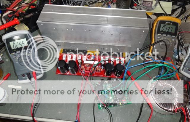
Here is a pic of the one channel running.
Blessings, Terry
I got one channel running. It is only at 37V rails right now for testing. One board has a problem but now that I have one good one I should be able to find it by comparing the two. I had the good one playing music for about 4 hours last night. I tried searching for the bias setting for this amp but got confused. Seems AndrewT and Carlos got in to an argument about how to go about setting it and the actual setting got lost in the fray. I set mine temporarily at 250ma at the rail fuse. That gave me about 25mv across one output emitter resistor. If one of you who have built this amp cold tell me how you went about setting it, I would be very grateful. I also have about 34mvdc on the output. I did match the LTP devices by hFE. Is there something else I can do to bring this down a little?
Here is a pic of the one channel running.
Blessings, Terry
An externally hosted image should be here but it was not working when we last tested it.
Mister Carlos post that here on post #3
all information about adjustment is there.
I did it in 2011 with +55V 0 -55V power supply and I was able to adjust the BIAS to 1mV maybe is different using the correct power supply (64V) but remember I know you are testing with a lower voltage power supply but the adjustment has to be done with the toroidal transformer you are going to use, the “permanent” one, also you got to wait a few minutes until temperature to be stable then keep adjusting until you get about 1mV.
the way Carlos explain me is that is the "stand by current" to the lowest power consumption of the amp" so the amp at (stand by) will not get hot or better say is not consuming much power at that stage, I hope you can understand that my English is not that great to explain that lol, ok before Carlos jump on me and kill me jejejeje this is the way I see it or better said I comprehend how BIAS work maybe is different for other guys so yeah that is how I see it,
so far I have BIAS 4 Dx amp models Dx Blame ST,Dx Blame MIKII Supercharged,Dx MKIII, and now Dx Super A same concept. the output reading should be at AC reading on the multimeter the output should read about 0V no voltage should present there with no input signal of any kind, I mean is not going to be perfect "0" maybe some mV 0.04 mV perhaps less.
Regards
Juan
Last edited:
Ohooo! I see what happen the first time I did was reading from the emitter resistor but can be done reading from the 100 ohms resistors where the fuse goes
too.
I'm sorry I don't want to confuse nobody I apologize,
but I guess there are too ways to do it, is cool
Regards
Juan
too.
I'm sorry I don't want to confuse nobody I apologize,
but I guess there are too ways to do it, is cool
Regards
Juan
Attachments
Last edited:
Hi Juan,
Yes I saw that post but I though he was just referring to initial start up. 43ma seems low. Almost every A/B amp I have built called for at least 100ma bias. I will back it down and see how it sounds.
Thanks, Terry
Hi Terry-
There is a wide variety of opinion on biasing this amp. I went with the bias level recommended by Doug Self in his book. As I remember that's about 57 mv measured across 2 emitter resistors. I also found that this level of bias results in the lowest measured THD. It is true that the amp will run hotter than it does at Carlos' recommended bias. Judging by the picture of your heat sink I doubt you have any reason to worry about the extra heat. Mine are much less impressive looking and my amp runs fine with 75v rails.
Thanks guys.
I got the second channel figured out. I had installed 8R2 where I needed 8K2. Funny what you can find with an ohm meter.
Funny thing is that this channel has a much lower offset, only 9mv. I tried hooking each of them up to my bigger transformer but the first on I had working has a problem now in that the bias won't stay. It just keep rising. When it got to about 350ma I shut it down and just set it aside. The one I just fixed however is working flawlessly. It is playing beautiful music as I type this. Now to take some measurements on it so I can figure out what is wrong with the other.
Well I found the problem with my second channel. I had 8r2 where I supposed to have 8K2. Funny thing is this channel has only 9mvdc offset. So now that I've got them both working, I hook up my bigger transformer with four 10,000 caps and hooked up the first channel. Well, not so good. I have the bias pot all the way up and I can't stop the amps from rising so I shut it down. I put it aside and hookup the channel I just fixed and carefully bring it up on the variac. No problems. I can actually set the bias to 100ma which gives me about 16mv across an output pair. I did notice the offset rising and got all the way up to 40mvdc when I felt the VAS heatsink and it was very hot. I grabbed a little fan and put it on the VAS and the offset dropped back down to 9mv. Looks like I will need to put a much larger sink there. I've had it playing for an hour now and everything looks and sound really good. Now to take some voltage measurements so I can figure out what is wrong with the first channel.
Blessings, Terry

This is great mister Terry so one channel had a 8R2 instead of 8K2 ? so how about the sound did you notice that it has a special sound? is different I don't know how to described, but is strong and with lot of melody, I'm glad you getting into it
Regards
Juan
Regards
Juan
Last edited:
Sorry Juan, I can't really tell yet. It is playing through my test speakers and only one side of the music. I'm looking forward to hearing it in a proper condition. I've a bit of work to do on it tomorrow to find the problem. I started today but I must get the pcb info and schematic together so I can get the voltages written down and be able to try an figure where it is going awry. Fun stuff!
Ha, you know the bad thing is I did that very thing with every one but these two. I filled the two boards one value at a time. Unfortunately, I was missing two of the 8K2 resistors and had to order them. When the order came in I just grabbed the envelope that I thought was 8K2, pulled out two resistors and soldered them in. All that care I took was nullified by carelessly rushing a week later. Fortunately, I learned long ago to use a variac and lightbulb and approach start up very slowly and watch for smoke.
Skilled guy..... you will find all mistakes and fast
Everything gonna be all rigth..for sure it will.
You know we make mistakes...this is the most important thing...knowing, we go to search in the place to be sad.
Also, a simple amplifier alike that will never be a challenge to you.... easy to you....you do that with one eye open and the other sleeping.
regards,
Carlos
Last edited:
" I did notice the offset rising and got all the way up to 40mvdc when I felt the VAS heatsink and it was very hot. I grabbed a little fan and put it on the VAS and the offset dropped back down to 9mv. Looks like I will need to put a much larger sink there. I've had it playing for an hour now and everything looks and sound really good. Now to take some voltage measurements so I can figure out what is wrong with the first channel."
Blessings, Terry
Hi Terry-
I don't think your problem is the VAS heatsink. I use the same one and it never gets hot. I remember that some builders noted a jump in bias current as the pot was adjusted upward. It turned out that those amps were breaking into oscillation. If you have a scope you should be able to see this on the outputs if it's happening. If you rule out oscillation check for an incorrect component or wiring error around the VAS or bias generator.
Good hunting
Steve
Hi bonfis,
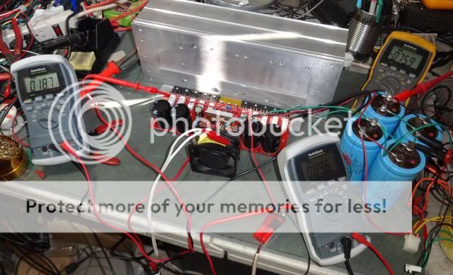
I didn't use the normal heatsink on my vas. I used a single sheet of aluminum. I didn't realize how hot the VAS runs. I have made a large heatsink to try. It ran fine with the small fan you can see in the pic above. I checked both boards side by side this morning at a lower voltage so it wouldn't over heat and they are fairly close to each other. The problem seems to be that something changes when run at the higher rails. On both boards, I have to have the bias pot at it's highest resistance to keep the bias under control. Is it possible that I need to increase R21? Is there something else that may need to be changed to run at the higher rails?
Thanks, Terry
- Status
- Not open for further replies.
- Home
- Amplifiers
- Solid State
- Dx Blame MKIII-Hx - Builder's thread