radioFlash, how did you solder the output transistors into position, with this single sided board?
What are the main differences between this layout and the previous ones? I notice there is space for 4 filter caps instead of 2.
What are people's opinions on mounting large caps on their side, with the board mounted flat against the heat sink as shown above? I am thinking about having some smaller 1000-2200uF caps on the board and a separate bank of filter caps after the transformer.
The official layout, tested by me is the one Alex mm made
and the one Meanman has made....also Byron made one that was tested too....others may be good...or not.... can be even better...can be even worse.
I cannot give you guarantee if you decide to build other layouts... doing this, if something happens, go to the layout designer and ask him what is going on.
I use to test all layouts, because this use to be very critical and ask for a lot of caution...it is not only pretty that results good...lenght of copper tracks (inductance), how distant they are one related the other (capacitance) and several other details related magnetic pickup.
Independent layout designers can publish in this same thread...but this does not mean that have my blessing and support.
regards,
Carlos
I found my error: I copied a resistor value incorrectly and used 4.7K instead of 4.7 ohms for R22. Attached is a PDF with the corrected version of my schematic and layout. No more DC offset.
Carlos:
Thanks for working on and sharing the design for this amp. The layout you and AlexMM came out with is very nice. I created my own for fun and practice. As you say, it is not an official layout and I won't expect you to help troubleshoot.
Ranchu:
This is what I did to solder the output transistors:
* Insert the transistors into the board without soldering.
* Screw the board down and position the transistors.
* Heat the middle leg of the transistor and flow some solder on it. The solder actually flowed down through the hole enough to hold the transistor in place for me to remove the board and solder the other pins. Instead of this, you could try soldering the middle leg to the board before screwing the board to the heatsink and reflow the solder while positioning the transistor.
* Screw the board back to the heatsink, screw down the transistors, and reflow the solder in each of the legs to relieve any stress.
This was based on a suggestion from AndrewT on another thread.
My board is slightly narrower (10 inches) to fit on my heatsink. I also added space for a clamping diode (D5 in my schematic). Also, I don't have provisions for multiple sizes of input capacitors the way AlexMM's layout has.
Attachments
I did some tests with a 1khz signal and see some oscillations on the positive swing. I recall that some others had this issue in this thread--I'll have to read back to see what was done about it.
Attachments
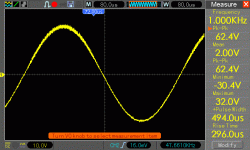
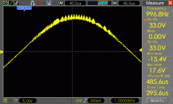
I did some tests with a 1khz signal and see some oscillations on the positive swing. I recall that some others had this issue in this thread--I'll have to read back to see what was done about it.
Yes we did. The oscillations were tamed in my case by increasing the value of the base stopper resistors. If i recall correctly (something that's becoming rarer these days) the value was approximately doubled. In any case if you search this thread for my postings you will find all the specifics. There were other changes I made to reduce the amps overall gain that might also interest some builders. Good Luck.
Hi Bonfis,
I remember you and Cannonica doing the ground work on this , maybe Carlos or meanman can document the updated modifications making it standard fare for those getting in on the new group offerings ..,
@Carlos,
Are there any upgrades /Mods from the Brazilian Corp on the Mk3 carlos ..?
I remember you and Cannonica doing the ground work on this , maybe Carlos or meanman can document the updated modifications making it standard fare for those getting in on the new group offerings ..,
@Carlos,
Are there any upgrades /Mods from the Brazilian Corp on the Mk3 carlos ..?
bonfis said he increased the base stopper resistors from 22 ohms to 56 ohms. I will need to give that a try.
bonfis' comments about increasing the stopper resistor: http://www.diyaudio.com/forums/solid-state/193759-dx-blame-mkiii-hx-builders-thread-130.html#post3069106
bonfis' comments about increasing the stopper resistor: http://www.diyaudio.com/forums/solid-state/193759-dx-blame-mkiii-hx-builders-thread-130.html#post3069106
to cancel negative impedance that is sometimes refected back from an unusual load.
By adding in pads for a base resistor it allows the option to fit a base resistor. You still have the option to link across the pads.
I now recommend base resistor pads for all outputs, drivers and pre-drivers, if fitted.
By adding in pads for a base resistor it allows the option to fit a base resistor. You still have the option to link across the pads.
I now recommend base resistor pads for all outputs, drivers and pre-drivers, if fitted.
This amplifier, alike almost all my amplifiers, alike almost all audio community
have Doctor Self (and some others of the same level) as our Gurú, our reference, our scientist, our best name.
This amplifier was "inspired" in Doctor Self Blameless, that was a concept, something basic that was published to give us the clue about what is the good sounding device....the low THD, IMD and some other artifacts that stain the audio quality.
The basic amplifier, because the culture present at the time of release, was considered too much precise not having the colourations of sound we use to listen...so, was considered something as "sterile", without spice..... a sound that could not move our hearts...and this was mentioned by Doctor..he said was the base to improovements and not a real amplifier... a concept...the differential with some enhancements, the VAS with some enhancements and the darlington emitter follower output...just the frame, the skeleton, the topology.... Self has not create or discovered ( i suppose, not sure) the differential amplifier...so..he does not own this...also he has not create the Voltage Amplifier Stage...also does not belongs to him...he also does not create Darlington circuits...was Dr. Darlington (dead poor, and lonely, his patent gone to his company..Bell Telephone Co.).
So, the stages included in the Blameless are not his discovery.... the idea of low THD, TIM, IMD and some other things that i have not all that deep understanding, is what belongs to him...the CONCEPT, as the English Gentleman said, ... WE, users and DIYers ...we are in charge to develop.
I have made a lot of modifications (naturally the ones does not like me try to say i made a make up).., some minor other major modifications....just compare circuits and you gonna see it was deeply "tuned" for sound reproduction, and the same Blameless reference of topology had different sonic signatures in each one of all my amplifier models...so.... was shown and proved we can change, we can modify and we can give it the character we want and we need...... if guys can be positive, may say it was evoluted, the ones wants say bad things will say they are "coloured"....this depends on your mood of the one analise the stuff..
Resistors added in series to the bases are called "stop" resistors, and they help you to "control" the inter electrodic capacitance you find in transistor base to emitter junction... this helps to avoid, or to cancell oscilations.....turning the system more stable.
Everything added has a reason.... some of them are because of sound tests..other because discoveries made, even by Self, along his long and brilliant research.... the ones does not like uncle charlie, will say my modifications are randomic and fashion....i would say they feel envy on me.
My respect to this great man....Doctor Douglas Self!
Dx Boom, another self inspired amplifier.... recently got out from the oven...enjoy folks:
Dx Boom 1 - YouTube
Picture is Sidney Darlington!
regards,
Carlos
Attachments

Last edited:
Please folks...take some time to read about Blameless
Dx .... Blameless STYLE in audio amplifiers
Dx is Blameless copy - YouTube
search for Doctor Self pages.
regards,
Carlos
Dx .... Blameless STYLE in audio amplifiers
Dx is Blameless copy - YouTube
search for Doctor Self pages.
regards,
Carlos
Hi still4given
What attracts me to these DX amplifiers is not their technical performance (which may be excellent; unfortunately I am too inexperienced to pass judgement) but the energy, drive and good humor of the creator, Carlos.
I suppose there wouldn't be much to talk about on this forum if the only interest was the pursuit of measurable, technical perfection. I guess people would quickly converge on a couple of key approaches and all other designs would be minor variations thereof.
Yes forgiven.... i agree.
I cannot do different...it is not exaclty that i dislike the old ones...i just cannot use my time on them anymore...or...no new one will be released.
We cannot stay in the past... sadly.... we cannot...we have to march into the future...the watch never stops.
regards,
Carlos
I cannot do different...it is not exaclty that i dislike the old ones...i just cannot use my time on them anymore...or...no new one will be released.
We cannot stay in the past... sadly.... we cannot...we have to march into the future...the watch never stops.
regards,
Carlos
I cannot do different...it is not exaclty that i dislike the old ones...i just cannot use my time on them anymore...or...no new one will be released.
We cannot stay in the past... sadly.... we cannot...we have to march into the future...the watch never stops.
regards,
Carlos
Will you create a low power amplifier like 60 watts R.M.S using just two output transistors per channel and using as fewer parts as possible in the future?. it will be nice to see a simple and well designed amplifier
") .
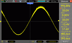
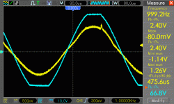
.Fixed my oscillations
Based on suggestions from bonfis, I increased the values of the base stopper resistors and decreased the gain.
R23a & b 22R -> 68R (base stoppers)
R9 390R-> 1.5K (to reduce gain)
This seems to have fixed my oscillations problems. Below are the results into a 4ohm resistive load using a 30-0-30 300 VA transformer (the only one I have handy at the moment) as well as the revised schematic/layout reflecting the changes.
Could I use a 60-0-60 transformer with this amp if I have 100V+ rated capacitors?
Attachments
- Status
- Not open for further replies.
- Home
- Amplifiers
- Solid State
- Dx Blame MKIII-Hx - Builder's thread