The most times Ive seen oscilations like that and at such a high frequency was due either to oscilation in a cascoded stage like the LTP or inductances in the outputs either through emitter resistors or layout. Be sure the emitter resistors are non inductive type, this is important and second cure is base resistors at drivers and outputs, the drivers are first suspects. Also check if LTP ccs is stable by checking the same frequency and placing a hand near the ccs transistors, just placing finger on top of the plastic of the transistor should do.
Thanks to all 3 of you for the suggestions. The ideas from Homemoder were especially interesting because I have a modified version of the amp that doesn't have this parasitic. The mods to that unit were almost entirely to the input LTP in order to reduce gain and included larger emitter resistors, increased standing current, larger input cap, larger base shunt cap to lower HF roll off and a feedback factor of 10:1. Otherwise that amp is identical to this one.to help our friend.... despite my home unit is not presenting troubles i would like to thank you very much.
regards,
Carlos
So I think I will try making the same mods one at a time and see what does the trick.
I'll get back with results.
Steve
Yes the output stage emitter resistors are metal oxide non-inductive. I don't have good equipment for transistor matching but they were all from the same batch. I could probably jury rig something to try and get them matched. I'm assuming you are referring to the small signal transistors in the LTP and current mirror. Is mismatch a likely source of parasitics?Steve,
Are you using non -inductive resistors , were your transistors matched?
Thanks
Steve
Mismatch leads to excessive output offset and excessive change in output offset with temperature and unbalanced currents lead to excessive distortion (that some might like).
As far as I know mismatch does not lead to oscillation.
Home,
how much is too much for inductance of the output emitter resistors.
Bon,
metal film and metal oxide and wire wound will all have a few turns of helix to create and trim the resistance. That always equates to some inductance.
The lead pitch also has some inherent inductance.
Cured the Oscillation
Increased the driver base resistors to 56 ohms and that did it. No more oscillations and a clean 10 Khz square wave response.
Thanks guys for all the help. I will be doing some comparison tests between this amp and my lower gain version. I plan to post the results for those using a preamp who might want to adjust the gain downward.
Steve
The most times Ive seen oscilations like that and at such a high frequency was due either to oscilation in a cascoded stage like the LTP or inductances in the outputs either through emitter resistors or layout. Be sure the emitter resistors are non inductive type, this is important and second cure is base resistors at drivers and outputs, the drivers are first suspects. Also check if LTP ccs is stable by checking the same frequency and placing a hand near the ccs transistors, just placing finger on top of the plastic of the transistor should do.
Increased the driver base resistors to 56 ohms and that did it. No more oscillations and a clean 10 Khz square wave response.
Thanks guys for all the help. I will be doing some comparison tests between this amp and my lower gain version. I plan to post the results for those using a preamp who might want to adjust the gain downward.
Steve
If you want to try one of previous amplifiers, then you have pcboards being offered
Be a Brazilian friend called Zimmer.
The Supercharged blue boards will cost 7 USD each one.....naturally you have shipment to include.... Zimmer said he has paypall.
I do not accept orders.... Zimmer is the one is receiving orders.... go directly and straight to Zimmer.
Boards are good to assemble four different models, including Dx Blame ST....you can see details here:
DX Blame Amplifiers - Carlos Mergulhão
Zimmer email:
imap.eletro@gmail.com
regards,
Carlos
Blame Dx MK III test results
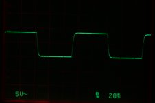
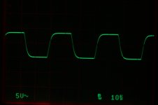
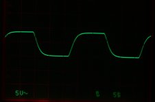
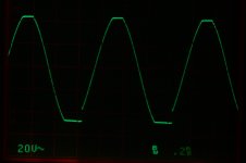
I have just completed some testing of a modified (lower gain) and unmodified Blame DX MK III. Both versions use 4 output pairs and have had driver base resistors increased to 56 ohms. See post 1212 for details of the modified version. Both produce their lowest measured distortion with about 56 mv of bias measured across both emitter resistors. 1 Khz THD into 8 ohms in the modified version is significantly lower by a factor of about 5 times at full power. This is presumably due to the higher feedback factor. Both sound very good to my ears.
See attached scope shots
Attachments
-
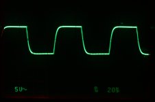 Orig 10 Khz.JPG263.9 KB · Views: 467
 -
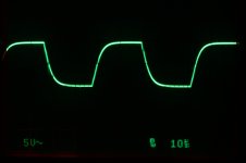 Orig 30 Khz.JPG259.4 KB · Views: 438
 -
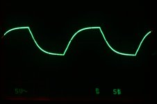 Orig 40 Khz.JPG261.4 KB · Views: 396
 -
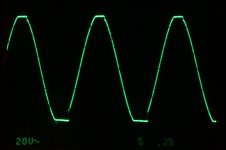 Orig Clipping.JPG270.4 KB · Views: 375
 -
 Mod 10 Khz.JPG518.4 KB · Views: 352
 -
 Mod 20 Khz.JPG521.2 KB · Views: 85
 -
 Mod 40 Khz.JPG519.5 KB · Views: 78
 -
 Mod Clipping.JPG530.2 KB · Views: 84

I had much better waveforms....but i cannot check this once more
because my scope is damaged.
I do think bias is too much high in level.
If this is good for him i feel happy.... the amplifier must fit his needs...if this way he likes..then i hope he enjoy.
I will not change the original schematic as i had not these troubles he informed.
regards,
Carlos
because my scope is damaged.
I do think bias is too much high in level.
If this is good for him i feel happy.... the amplifier must fit his needs...if this way he likes..then i hope he enjoy.
I will not change the original schematic as i had not these troubles he informed.
regards,
Carlos
because my scope is damaged.
I do think bias is too much high in level.
If this is good for him i feel happy.... the amplifier must fit his needs...if this way he likes..then i hope he enjoy.
I will not change the original schematic as i had not these troubles he informed.
regards,
Carlos
The bias level that produced the lowest distortion is very close to that identified by Dr.Self as optimal for EF output stages with .47 ohm emitter resistors (see page 183 of Audio Power Amplifier Design Handbook. It does result in more idle current than the recommended bias and consequently more heat so adequate heat sinking is required.
The issue of troubles with parasitics is a separate matter. If you are unable to view waveforms on a wide band scope you don't know if you have this problem. It seems reasonable to take the precaution of installing the higher value driver base resistors as a cheap form of insurance.
Steve
- Status
- Not open for further replies.
- Home
- Amplifiers
- Solid State
- Dx Blame MKIII-Hx - Builder's thread