Agree Steve ,
The focus Should be about making the amplifer technically sound and or mods for improvements , there is lot needed to be sorted a pity Andrew decided to use the low road
Keep posting with your measurements there is enuff experience here to sort this out , maybe the mods can remove the Mumbo jumbo posts ...
Just to be clear. I am reporting what I have found in the course of building and testing my Dx Blame. My hope is to perhaps get some help with the problems I have encountered and to better understand their cause. I am not in any way criticizing the amp or it's designer. Obviously many people have built this amp and are enjoying listening to it. That doesn't mean that their amps are free from the problems I have experienced. The parasitic oscillation I found is outside the range of human hearing and beyond what speakers can reproduce. That's why I asked if anyone else had checked their amp with a scope.
I liked the spirit of this thread when people started the group buy and began building. It would be great if it stayed positive and helpful. We are here to learn and enjoy, No?
Steve
I suggest you try using slightly higher value base resistors on those drivers, say from 22 to 47 ohm.
I suggest you try using slightly higher value base resistors on those drivers, say from 22 to 47 ohm.
I like that idea based on what I know about the function of base stopper resistors. I should point out that I have a modified Blame with changes noted in post 1212 that is free of oscillations. Those changes were made to reduce the amps gain since I drive the amp with a preamp. The feedback in that version is higher but the input stage transconductance is somewhat lower. 100 ohm emitter resistors instead of 68. Also the input hf roll-off was reduced in frequency by increasing C4 to 470 pf. I might try that C4 change first on this one in case some high freqs. are getting back through the input.
Steve
It is a good try anyway
I would like to see a picture....if a wale capacitor is in the input i will think we have found the guilty to blame..... because surface exposed to electro magnetic coupling ... because dimensions can tune (antena, aerial) radio frequency transmitters in the surroundings.... and some other things connected to SWR and RF tank circuits
regards,
Carlos
Last edited:
I would like to see a picture....if a wale capacitor is in the input i will think we have found the guilty to blame..... because surface exposed to electro magnetic coupling ... because dimensions can tune (antena, aerial) radio frequency transmitters in the surroundings.... and some other things connected to SWR and RF tank circuits
regards,
Carlos
No whale cap at the input. Just a guppy size 2.2 uf. No more than 1/2" square. I believe the electros are all at voltage ratings in original parts list but I'll check that. Will try to get pics up later in the week. Today's a work day
And please, let us know your results...inform the spurious frequency if possible.
regards,
Carlos
Frequency is approximately 4 Mhz. Checked all caps and they are standard per the parts list. No changes made at this point.
It seems unlikely that this oscillation is related to loop instability at so high a frequency. Do you agree? If it is purely a parasitic then I assume changing Cdom won't help. Any ideas for hunting down the source would be appreciated.
Steve
Usually oscilations are higher in frequency....i do not know what is this
I would use the try and error using the standard practices to cancell unstabilities....capacitors from base to colector, increase of Cdom, increase of stop resistors, reduction in gain and inclusion of NFB line capacitor.
Also the search of interferences... if using audio sources it would be good to inspect the input signal without plug it into the amplifier and then after plug it into the amplifier input.... the search of Radio Frequency oscilators around.... digital watch, electronic Baby sitter, wireless telephone...well...things that can use 1 Megahertz clock cristal multiplied by 4 or a real 4 MHz cristal instaled as clock oscilator.... well....i do think you already did that.
You know...try to reduce yourself to a non skilled guy...tben ask to yourself the question:
- What will happens if i do this?
Sometimes we discover things doing this way.
Once in my life i was inside Motorola repair place...for Portable Radio Transceivers...and someone use to beat all of us...we, a group of guys repairing...we used to analise and deduce, conclude, realise and then inspect...we use to delay 5 times when compared to that guy....then i decide to ask him what was making him so good.... so better than us....he said
- "I do not waste my time to be thinking..i go just removing transistors and testing them out from the board... and then one is shorted..then i substitute the one to know if there's another one...if no problem remain..then ready!"
The lesson i have learned was: "Be simple!"
Are you already simple?...be more!
regards,
Carlos
Last edited:
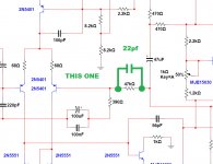
There's a resistor connected to the second differential transistor...the one is
connected to the output line...and there, in series with the output line you have a resistor.... attach a low value capacitor in paralell with this resistor..this will limit the frequency response and and gain in presence of high frequency signals that reaches or be developed in the output...it just reduces the audio bandwidth cutting out HF energy..... withing the spectrum of frequency you are facing.
3pf, 5pf,7pf,10pf,12pf,15pf,18pf and 22pf are values more often used.... i suggest you to try the highest one because your frequency is low inside the HF spectrum (3 to 30 Megahertz aprox.)
This is called NFB (Negative Feedback Line).... so, it is the output line that has a more sophisticated name....i use to be simple.... output line is the way i call it.
Surgery i have made is called by Doctors as Dermolipectomy...i call this "removing excess of skin."
This works in a very simple way.... radio frequencies due to oscilations, or signal picked by antenna (audio cable) is present in the output line, or NFB line.... then it crosses the capacitor that is a short for such kind of frequencies and drives, as a result, the second differential transistor that automatically reduces the gain of this differential pair.... when oscilations are because of gain..then the trouble is fixed.... when the signal present is picked, then the reduction of gain makes it small in order you cannot see it superimposed to the scope scanning line...if you cannot see it..then it does not bother you and you go in peace living with the spurious without knowing it is there.
regards,
Carlos
Attachments
Last edited:
Introducing this extra capacitor often leads to extra or worse oscillation of the amplifier.
not as little as "sometimes".sometimes goes worse
Happened once that oscillated even worse.
More likely to be "often", particularly if one guesses at a value without realising why that capacitor should or should not be there.
- Status
- Not open for further replies.
- Home
- Amplifiers
- Solid State
- Dx Blame MKIII-Hx - Builder's thread