I won't argue on subjective topics. I did my homework and came with objective results.
Refer to the image below...
The offset test was made with the signal input leads shorted. I did it both with the real physical 42pounds heavy amplifier, and with the simulator. BOTH gave the same results...
There IS a DC offset voltage at the input transistor's base. The input cap DO block this from getting back in your source.
By removing the cap, that DC offset will leak to the ground and its amplitude be altered thus changing the stability of the speaker-out's offset.
Furthermore if, like me, you have an input pot to control the input sensitivity, turning it will change the resistance of the circuit (input DC offset to ground) and will alter greatly the DC offset at speaker-out. Turning that input pot makes the speaker go in and out like crazy, I guess the output varies by many volts .
Do your own tests my friend... and you will see.
I got to report this because other people may be tempted to remove the input cap and they risk breaking something. This amp cannot run directly coupled to a source
Attachments
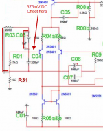
375mVdc of input offset across 47k indicates that a fairly high current is flowing from the base of the input transistor. It also indicates a low input impedance to the amplifier input stage.
That can be explained by the choice of 2n5401 as the input transistors.
Do you know the hFE of the input transistor/s that you used?
That can be explained by the choice of 2n5401 as the input transistors.
Do you know the hFE of the input transistor/s that you used?
I won't argue on subjective topics. I did my homework and came with objective results.
Refer to the image below...
The offset test was made with the signal input leads shorted. I did it both with the real physical 42pounds heavy amplifier, and with the simulator. BOTH gave the same results...
There IS a DC offset voltage at the input transistor's base. The input cap DO block this from getting back in your source.
By removing the cap, that DC offset will leak to the ground and its amplitude be altered thus changing the stability of the speaker-out's offset.
Furthermore if, like me, you have an input pot to control the input sensitivity, turning it will change the resistance of the circuit (input DC offset to ground) and will alter greatly the DC offset at speaker-out. Turning that input pot makes the speaker go in and out like crazy, I guess the output varies by many volts .
Do your own tests my friend... and you will see.
I got to report this because other people may be tempted to remove the input cap and they risk breaking something. This amp cannot run directly coupled to a source
Martin ,
Andrews rhetoric aside , there was no put down , my response was that of suprise and thanks for clarifying the results ...
Canon,
well argued. Don't let them put you down when you have the evidence to support your conclusions and/or statements.
I would rather have music than broken equipment.
In my book "broken equipment" can never reproduce as well as working equipment.
I would rather you answer direct questions instead of flying in with your girlish retorts, Instead you take every chance you get for personal insults, even took time to hurl one at Carlos ...
Silly Rabbit .....
 .
.Canon,
well argued. Don't let them put you down when you have the evidence to support your conclusions and/or statements.
I would rather have music than broken equipment.
In my book "broken equipment" can never reproduce as well as working equipment.
What about bad music ...?
375mVdc of input offset across 47k indicates that a fairly high current is flowing from the base of the input transistor. It also indicates a low input impedance to the amplifier input stage.
That can be explained by the choice of 2n5401 as the input transistors.
Do you know the hFE of the input transistor/s that you used?
What would you change it to ..?

What voltage are you operating the amp at Martin ....?
64VDC plus 64VDC
I take exception to Carlos' claims............ personal insults, even took time to hurl one at Carlos ...
I rubbish his behaviour.
I have done it in the past and where/when necessary, I will repeat my confirmation where there are mistakes or bad choices or downright lies.
Output stage bias
Back with more questions...
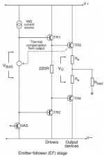
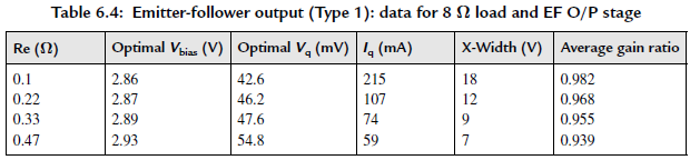
The output stage bias. Carlos mentioned a way to adjust it: measure the voltage drop across output resistor to obtain 1mV. However in the emitter-follower configuration like the HX, Dr. Self has determined that optimum is very far from that value.
Dr. Self suggest a voltage drop of about 27mV across those 0.47r resistors... Am I missing something, or based on this, Is my amp very underbiased with that 1mV drop??
Please see the pics below that are from Dr. Self's book...
Martin.
Back with more questions...
The output stage bias. Carlos mentioned a way to adjust it: measure the voltage drop across output resistor to obtain 1mV. However in the emitter-follower configuration like the HX, Dr. Self has determined that optimum is very far from that value.
Dr. Self suggest a voltage drop of about 27mV across those 0.47r resistors... Am I missing something, or based on this, Is my amp very underbiased with that 1mV drop??
Please see the pics below that are from Dr. Self's book...
Martin.
Attachments
Since I can't measure output distortion, I rely on the Vre method for optimum ClassAB for output bias setting, unless the designer tells me otherwise.
You have to decide how close the amp output stage is to similar designs where the "professional designers" tell us of their method in comparison to Carlos' DX amp.
You have to decide who to put your faith in.
You have to decide how close the amp output stage is to similar designs where the "professional designers" tell us of their method in comparison to Carlos' DX amp.
You have to decide who to put your faith in.
Hmmmm...
I did some testing increasing the quiescent current (bias) measuring the Vq that crosses the two emitter resistors (to prevent getting skewed by any offset).
When I gently increase the bias current, it gradually goes up to 43mV, then suddenly jumps to 140mV. Then I turn the other way around and it gently descent down to 110mV, then suddenly jumps to 30mV. I have to go back many turns to get back below the 110mV mark.
Looks like past 43mV, something is triggered that makes the quiescent current jump all in a sudden.
That was for one card, for the other, when I reach 35mV it jumps to 165mV, then when I go back it jumps from 80mV to 6mV...
Anybody have a clue for me?
Thanks,
Martin.
BTW, I checked for some "consumer" amps, and for example the Adcom GFA-555, the measured voltage drop across on resistor should be set to 16mV cold, resistor is 0.82r
The parameters of the output stage are changing.
The drivers and/or the outputs are going into oscillation.
The DX range of amplifiers are not designed in the conventional manner. They were put together with guesswork based on listening tests. Stability is not guaranteed.
The drivers and/or the outputs are going into oscillation.
The DX range of amplifiers are not designed in the conventional manner. They were put together with guesswork based on listening tests. Stability is not guaranteed.
Well, compared to the base design of Self's amps, the Hx is not totally different. This abrupt jump of emitter bias voltage is so unexpected that I'm wondering of the problem resides onto the design itself or onto components that reaches a breakdown point.
Il the simulator, I cannot reproduce that behavior, I can increment from a few uV to about 350mV without any jump.
I cannot agree with your comment "put together with guesswork". Dx did apply Self's "best practices" and he fine-tuned some values by ear. Look at the schematics of the Hx and compare it to Self's base amp... I don't speak about the Es amp Dx has put out, it was ... well, not good.
Still if someone else increases its bias voltage, please post results.
Martin.
Oscillations, 100%.
Hmmmm...
I did some testing increasing the quiescent current (bias) measuring the Vq that crosses the two emitter resistors (to prevent getting skewed by any offset).
When I gently increase the bias current, it gradually goes up to 43mV, then suddenly jumps to 140mV. Then I turn the other way around and it gently descent down to 110mV, then suddenly jumps to 30mV. I have to go back many turns to get back below the 110mV mark.
Looks like past 43mV, something is triggered that makes the quiescent current jump all in a sudden.
That was for one card, for the other, when I reach 35mV it jumps to 165mV, then when I go back it jumps from 80mV to 6mV...
Anybody have a clue for me?
Thanks,
Martin.
BTW, I checked for some "consumer" amps, and for example the Adcom GFA-555, the measured voltage drop across on resistor should be set to 16mV cold, resistor is 0.82r
Well, compared to the base design of Self's amps, the Hx is not totally different. This abrupt jump of emitter bias voltage is so unexpected that I'm wondering of the problem resides onto the design itself or onto components that reaches a breakdown point.
Il the simulator, I cannot reproduce that behavior, I can increment from a few uV to about 350mV without any jump.
I cannot agree with your comment "put together with guesswork". Dx did apply Self's "best practices" and he fine-tuned some values by ear. Look at the schematics of the Hx and compare it to Self's base amp... I don't speak about the Es amp Dx has put out, it was ... well, not good.
Still if someone else increases its bias voltage, please post results.
Martin.
Did you use matched outputs/drivers .....?
- Status
- Not open for further replies.
- Home
- Amplifiers
- Solid State
- Dx Blame MKIII-Hx - Builder's thread