Already made SoftStart
Because I couldn't find any open group-buy for a softstart, I've searched something "ready-to-run" and found this: Softstart
They also have speaker protection circuits that seems to fit what I need in that matter. One unit is good for two channels. I worry about the channel separation, but at that price I 'm gonna order two of them, one per channel: LS-Prot
Seems to be what I need. I've not ordered yet though.
Martin.
Last edited:
") ..
..
Rudy,
Thank you for the offer to send me the Eagle files for your softstart board. After the last group buy, I'm pretty much burned-out on group buys. They are a lot of work. Also, as soon as I got my first response, I ordered the Elliot Sound Products softstart boards right away.
Thank you for the offer to send me the Eagle files for your softstart board. After the last group buy, I'm pretty much burned-out on group buys. They are a lot of work. Also, as soon as I got my first response, I ordered the Elliot Sound Products softstart boards right away.
My slow progress
I had a few distractions keeping me from my amplifier. I can't complain. One of them was a cousin's wedding .
.
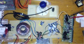
I was able to power up and set the bias current to 4.4V. I didn't want to build a bulb tester (I think of it more as impatience than laziness) but everyone in the thread, and everything I read about power supplies said "BULD A BULB TESTER! BUILD A BULB TESTER!" So, fine, I spent an afternoon building a bulb tester from spare parts from home-improvement projects.
I had the board powered up with the 100R resistors for quite a while as I set the bias andchecked for excessive heat. Only those 2 transistors in the middle of the board got hot - the ones Carlos said would get hot. I didn't have heatsinks on them because I didn't think ahead to buy nylon screws, and didn't want to risk an accidental short. When the nylon screws arrive Wednesday, I'll try putting an 8 ohm resistor across the speaker terminals. If all goes well, it will make some noise through a speaker tomorrow!
Here's the link to the chassis I chose.
eBay - New & used electronics, cars, apparel, collectibles, sporting goods & more at low prices
It's made by Par-Metal, even though it's not listed on their web site. Only sold through e-bay. Everything will just barely fit!
I had a few distractions keeping me from my amplifier. I can't complain. One of them was a cousin's wedding
.I was able to power up and set the bias current to 4.4V. I didn't want to build a bulb tester (I think of it more as impatience than laziness) but everyone in the thread, and everything I read about power supplies said "BULD A BULB TESTER! BUILD A BULB TESTER!" So, fine, I spent an afternoon building a bulb tester from spare parts from home-improvement projects.
I had the board powered up with the 100R resistors for quite a while as I set the bias andchecked for excessive heat. Only those 2 transistors in the middle of the board got hot - the ones Carlos said would get hot. I didn't have heatsinks on them because I didn't think ahead to buy nylon screws, and didn't want to risk an accidental short. When the nylon screws arrive Wednesday, I'll try putting an 8 ohm resistor across the speaker terminals. If all goes well, it will make some noise through a speaker tomorrow!
Here's the link to the chassis I chose.
eBay - New & used electronics, cars, apparel, collectibles, sporting goods & more at low prices
It's made by Par-Metal, even though it's not listed on their web site. Only sold through e-bay.
Everything will just barely fit!Attachments
Speaker Prot
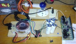
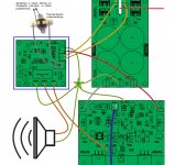
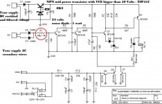
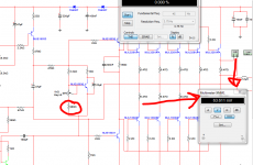
Hello Uncle Charlie, I want to use Migs Nabuco speaker prot as shown in below photo (enclosed in blue). Please let me know any modification in protection circuit so it will work in Blame MkIII. Thanks in advance.
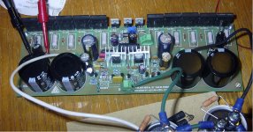
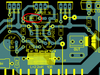
You see the white thick line is the transformer secondary center tap...it is not made as the star ground central point.... was used a more centralized idea..and works perfectly both ways.
regards,
Carlos
Hello Uncle Charlie, I want to use Migs Nabuco speaker prot as shown in below photo (enclosed in blue). Please let me know any modification in protection circuit so it will work in Blame MkIII. Thanks in advance.
Attachments
I have used this board only once .... i cannot remember details
So, if you have any doubt, then go to Mitchel and he will gladly help you:
miguelnabuco@terra.com.br
Mitchel was in charge to provide schematic, board layout, pcboards and support to this protector and also a surge unit that was offered only to Brazilians (surge)... then, latter and inside this same forum, he offered protector together the blue boards for the Supercharged (multimodel pcboard) and he supressed the surge board because of copyright issues... and have maintained the protector boards being offered in group buys in Brasil and also in this forum.... he was in charge to explain, to give support, follow up and guarantee of reliability to these extra boards...i have just asked him to test prior to deliver to the ones have ordered and i have built and tested myself too..... so... i do not know details about.... Miguel Nabuco (Mitchel) is the one is responsible by these boards....none of these boards are available.
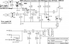
I have made minor changes to use higher voltage supply, i suppose BC transistors will fit.....maybe you will need to replace using 2N5551/2N5401 or other higher voltage, general purpose, transistors.
If you have these boards, then observe the BC546/556 have colector and emitter pins inverted one related the other.... watching the transistor in the reading position (leads downwards) the BC546/556 is readed as colector-base-emitter...and the 2N5401/5551 is readed as emitter-base-colector.
These boards are made to use one board to protect a single channel.... so, to have stereo you will need two of these boards... relay is a 24 volts unit... and you will need a huge relay because your audio current will be really big... if not easy to find a good relay, then use these original relay contacts to swith another bigger relay coil..then you should wire your speaker into that second bigger relay.
Condenser C7 must be a 64 volts or higher insulating voltage unit.... series pass transistor may dissipate 4.5 watts, so, it will need a heatsink.
Thermal sensor can be supressed...i am using without the thermal sensor.
I am attaching an image.
regards,
Carlos
So, if you have any doubt, then go to Mitchel and he will gladly help you:
miguelnabuco@terra.com.br
Mitchel was in charge to provide schematic, board layout, pcboards and support to this protector and also a surge unit that was offered only to Brazilians (surge)... then, latter and inside this same forum, he offered protector together the blue boards for the Supercharged (multimodel pcboard) and he supressed the surge board because of copyright issues... and have maintained the protector boards being offered in group buys in Brasil and also in this forum.... he was in charge to explain, to give support, follow up and guarantee of reliability to these extra boards...i have just asked him to test prior to deliver to the ones have ordered and i have built and tested myself too..... so... i do not know details about.... Miguel Nabuco (Mitchel) is the one is responsible by these boards....none of these boards are available.
I have made minor changes to use higher voltage supply, i suppose BC transistors will fit.....maybe you will need to replace using 2N5551/2N5401 or other higher voltage, general purpose, transistors.
If you have these boards, then observe the BC546/556 have colector and emitter pins inverted one related the other.... watching the transistor in the reading position (leads downwards) the BC546/556 is readed as colector-base-emitter...and the 2N5401/5551 is readed as emitter-base-colector.
These boards are made to use one board to protect a single channel.... so, to have stereo you will need two of these boards... relay is a 24 volts unit... and you will need a huge relay because your audio current will be really big... if not easy to find a good relay, then use these original relay contacts to swith another bigger relay coil..then you should wire your speaker into that second bigger relay.
Condenser C7 must be a 64 volts or higher insulating voltage unit.... series pass transistor may dissipate 4.5 watts, so, it will need a heatsink.
Thermal sensor can be supressed...i am using without the thermal sensor.
I am attaching an image.
regards,
Carlos
Attachments
Last edited:
Thank you very much for your early reply.
In the schematic you posted the AC input directly connected from the transformer secondary, do i need to change the value of R1? I've seen the protection circuit used before in Blame mkII supercharge or even Blame ST and using it in MkIII which is obviously with higher AC voltage?
In the schematic you posted the AC input directly connected from the transformer secondary, do i need to change the value of R1? I've seen the protection circuit used before in Blame mkII supercharge or even Blame ST and using it in MkIII which is obviously with higher AC voltage?
Attachments
I already asked this question, but I'll try one more time.
I like the profile for the heatsinks for the MJE15030 and MJE15033 transistors Alex drew in the silkscreen, but can't find them. Does anyone know of such heatsink? If not, what is everyone using?
-Byron
I'm not sure but I think this are the ones,
TO-220 Heatsink Voltage Regulator Isolation Kit 4 pcs | eBay
regards
vargasmongo
My board is not working
I suspect I damaged something on the board, but don't know where to start looking. Here is the whole story:
I would appreciate any suggestions about where to start troubleshooting. I've not started on the second board yet, but have at least 2 of everything.
I suspect I damaged something on the board, but don't know where to start looking. Here is the whole story:
- I thought I had my power supply working (which I later learned was not the case). I fired up the board for the first time without a bulb tester, which I hadn't built yet.
- I heard a brief crackling. I didn't see or smell smoke. I carefully checked for hot components and didn't find any, so I continued.
- I was trying to adjust the bias, but the board was not behaving as I expected. I don't remember what tipped me off, but I re-checked my power supply.
- I had two diodes on my rectifier flipped! I was sending AC through my filter caps and then, presumably, to the board. My multimeter measured this as about the correct DC voltage from rails to ground.
- I'm pretty confident I fixed my power supply, which measures ~59VDC positive-ground and ground-negative, and ~118VDC positive-negative. No AC voltage.
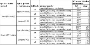
- I built a bulb tester and resumed setting the trimmer resistor. I found I could not get the voltage drop across the 100ohm test-resistor up to 4.4VDC.
- I thought that maybe I'm not supposed to have a jumper from signal ground to main ground, so I tried cutting it. I also thought maybe I needed an 8R resistor from speaker-out to ground. The included chart shows all the permutations, and the voltages I got for them.
- Typical test was: 1) put the light bulb in line and hook up the test leads. 2) Turn on. The bulb would glow brightly, then gradually dim. With the 8ohm resistor between speaker out-and ground it never dimmed completely. 3) Measured voltage would jump around at first, then slowly move to some final value, which is the value I recorded. 4) Bypass the lightbulb. Measured voltage would jump a bit, then settle on its new value.
- I removed and tested the trimmer resistor, and it works fine from 0 to 1020R.
I would appreciate any suggestions about where to start troubleshooting. I've not started on the second board yet, but have at least 2 of everything.
Attachments
Discard the 50W dummy load. It is drawing current to Audio Ground due to the output offset. No useful information in there as far as I can tell.
The open output and shorted input shows output offset. Can this be adjusted towards zerovolts?
Thankfully the offset is not near rail voltage. I think that is telling us that the outputs are not blown. Can you check current is flowing through every emitter resistor of the output stage. List all the Vdrops.
My Blame amplifier is not working uncle charlie!
Yep... sometimes this happens;
My Blame amplifier is not working uncle charlie! - YouTube
regards,
Carlos
Yep... sometimes this happens;
My Blame amplifier is not working uncle charlie! - YouTube
regards,
Carlos
I found a problem
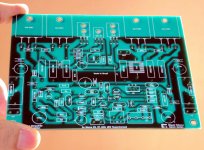
I don't know if it's the problem, but it's something. Two of the supplemental power supply filter caps - the big ones on either side of the board - are inconsistent. Sometimes they measure spot-on, and sometimes they give crazy values which are all over the place. They did this on the board, and after I took them off. Monday, I'll put back all the other components I removed to check and try again. And I'll try Andrew's suggestion.
I do have a question: There is a resistor right next to the trimmer pot. On my schematic I named it R21. Alex put the value 680R on the board, but Carlos' schematic shows 1200R. I used 1200R. I verified the value of it and all the resistors anywhere near that trimmer pot with my multimeter. Should I have used a lower value there, especially considering my <64V rail voltage? Presumably, that value of 1200R was chosen for 64V rails. If getting rid of these filter caps doesn't solve the problem, that will be plan B.
Thank you, everyone, for your suggestions.
-Byron
This resistor value is determined by the bias transistor chosen. See the attached pictures. I don't remember on what forum / page I picked these pics, but they come from DX-man himself about the Hx amp.
Martin.
Martin.
Attachments
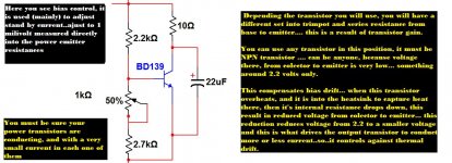
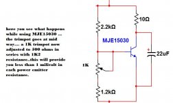
Thanks! I already have the NPN transistor MJE15030 so it should be 1.2KR instead of 680R. oh boy!This resistor value is determined by the bias transistor chosen. See the attached pictures. I don't remember on what forum / page I picked these pics, but they come from DX-man himself about the Hx amp.
Martin.
regards
vargasmongo
- Status
- Not open for further replies.
- Home
- Amplifiers
- Solid State
- Dx Blame MKIII-Hx - Builder's thread