Hi Juan,
I didn't understand Carlos to care that you change layout. It is the circuit that he wants preserved. I think it was Christian's suggestion of adding pre-buffers that concerned him.
It is hard to tell from the JPEG you attached above but it looks like your grounding scheme is slightly changed. If you remember earlier that we had to make some modifications to Alex's boards to get the lifted input ground to match the schematic. Maybe it would be good to do as Carlos suggested and go through the PCB with markers and double check that everything follows the schematic exactly.
Blessings, Terry
Last edited:
Post 2097 about the add of predrivers.
This is what switched on my reaction.
Anything about you Juan....i disagree to use predrivers.
I really become very nervous when people suggest modifications... even if i see they are in good will...and they were this way.. but looks very non sense to me....is alike an automobile that was designed, built and sold...thousands have bought and used.... approved by almost all users.... looks reliable and with good performance..them someone say.
- Cut it in half and put one more pair of doors.... and this means to make a new car from the original..to start all over again...in the reality a new project...so..in place to make a new one and people have, as a result, two cars...one model with three pairs of doors, the idea is to junk one project, to understand as not correct and create a new idea....maybe even better to the same automobile...and the automobile users..the ones bought the first model gonna be very disappointed.
I do not know if this is clear to you folks...at least it is totally clean as cristal to me.... it is alike to paint a moustache in Monalisa...so..no more Monalisa..... means destroy Monalisa.. after so many years considered a great art work, someone comes and paint a moustache, or suggest to remake Monalisa with a moustache.
My point of view still the same..it is not a new thing..you can read 10 years ago posting and you will see me reacting against this stuff... and criticizing people just producing "make up" in other guys work instead to create a new thing and instead to take to themselves the whole job to start all over again and to produce a new amplifier..their amplifier, applying their ideas.....you see, some guys did..i can point Ostripper and Bigun.. they have made new stuff instead to try to destroy my amplifiers to apply their ideas, they made their own and they took the responsability about their stuff..this is correct..not to be suggesting to kill an idea to apply their idea.
The guy that suggested, a very kind man, i do like him...i do think was Ranchu...no problem with him or against him....the problem i have is the idea that i do not accept to change the MKIII schematic to match his suggestion...not only his suggestion or any other one...i do think if people feel that can make it even better, then do not call it MKIII, then introduce the new stage, them test it, them develop and produce pcboards, them offer pcboards, them pack pcboards, then ship pcboards and do the whole thing instead to paint a moustache in Monalisa to make their own paint.
This way we gonna have a brand new amplifier, another amplifier, another approach, another idea...one more amplifier to the community instead to have an all patched schematic.... something never ending..as another guy will suggest something different in the differential, and another something different in the VAS...and this is another amplifier.
The message is.... "let this one in peace...make your own amplifier"
Got it?
Carlos
Last edited:
Hi Carlos
I understand completely you point of view and would like to withdraw my previous remark and apologise.
The DX MkIII is a very good amplifier - I have built one myself and the sonics are outstanding.
If people want to experiment by making modifications they should open their own thread and call it something else.
Thanks you Carlos for your wonderful contributions to the DIY community and ongoing support.
No need to apologize dear Ranchu...i know you made it in good will
For sure you will not believe but i can sense here the mood when i concentrate in someone name, post, home, local or any real world connection to the soul.
I want to stimulate people to do their own amplifier and leave this one alone...there are plenty of room for people to make research...you can use this amplifier if you want and introduce the stage you suggest..and create the Ranchu MK4 or anything...this is free to everybody...you see...a lot of guys do that in our forum...it is a normal and common practice.
My point is "not to destroy one to create another"...better to create another without destroy the one.
The insertion of another stage in the EF output will produce huge differences ( i do not like...reason why i have not implement it in any amplifier from the Dx line)..the amplifier will be a new one....another one...even if your resistor values and transistor brand names and capacitors being the same..also the same voltage.... even this way it gonna have a very different performance and gonna be another amplifier...one more amplifier....one more option to folks.
You can see me creating some troubles when the guy copy my amplifier to produce money.....this drives me to fight and be rude and make accusation and point finger and take the risk to be banished from forum because i do attack with full throotle....i do think all my efforts places to the community enjoyment should not be transformed into the dirt money..something i made for free, and to be shared to the whole world...something i give up to earn money from it.... something i have spent my money to produce...cannot be a merchandise.... this is not correct, i do not agree and i gonna do all i can to kick the one, to bother till the guy give up to get our from my sight or from our forum....... even knowing that they will be victim of the same evil i was victim.... pirates will copy their copy and will sell their copy in Asia the same way they made with me..so...they will, at the end, receive their punishment...they gonna have unbeatable competitors that gonna sell their stuff by 10 times lower price, including pcboards, parts, shipment and sometimes they sell the stuff already assembled ..this is a kind of sweet revenge i wish to see..and for sure gonna see... then Uncle Charlie will raise a glass of wine in their honor by doing justice and punish such indecent people
Go there, open a thread...simulate your MKXXX, copy my stuff if you want and produce yours..no problems....will be another amplifier..and as you gonna do for sharing i will not mind about that....but if start to sell..then i gonna become mad.
You can do...Juan can do...everyone can do....
But please...let the MKIII in peace..if suggestion is to change a value of resistor, or to change a value of capacitor..if it is tuning....it is all right..if people suggest to use other transistors...all right too...if change voltage in the supply..also all right if the one that make it say the troubles this can produce to the output transistors performance/dissipation and so on.... but do not suggest things that will result in another circuit, another amplifier and another layout, and another pcboard...please...let this one alone dear friends.
regards,
Carlos
For sure you will not believe but i can sense here the mood when i concentrate in someone name, post, home, local or any real world connection to the soul.
I want to stimulate people to do their own amplifier and leave this one alone...there are plenty of room for people to make research...you can use this amplifier if you want and introduce the stage you suggest..and create the Ranchu MK4 or anything...this is free to everybody...you see...a lot of guys do that in our forum...it is a normal and common practice.
My point is "not to destroy one to create another"...better to create another without destroy the one.
The insertion of another stage in the EF output will produce huge differences ( i do not like...reason why i have not implement it in any amplifier from the Dx line)..the amplifier will be a new one....another one...even if your resistor values and transistor brand names and capacitors being the same..also the same voltage.... even this way it gonna have a very different performance and gonna be another amplifier...one more amplifier....one more option to folks.
You can see me creating some troubles when the guy copy my amplifier to produce money.....this drives me to fight and be rude and make accusation and point finger and take the risk to be banished from forum because i do attack with full throotle....i do think all my efforts places to the community enjoyment should not be transformed into the dirt money..something i made for free, and to be shared to the whole world...something i give up to earn money from it.... something i have spent my money to produce...cannot be a merchandise.... this is not correct, i do not agree and i gonna do all i can to kick the one, to bother till the guy give up to get our from my sight or from our forum....... even knowing that they will be victim of the same evil i was victim.... pirates will copy their copy and will sell their copy in Asia the same way they made with me..so...they will, at the end, receive their punishment...they gonna have unbeatable competitors that gonna sell their stuff by 10 times lower price, including pcboards, parts, shipment and sometimes they sell the stuff already assembled
..this is a kind of sweet revenge i wish to see..and for sure gonna see... then Uncle Charlie will raise a glass of wine in their honor by doing justice and punish such indecent peopleGo there, open a thread...simulate your MKXXX, copy my stuff if you want and produce yours..no problems....will be another amplifier..and as you gonna do for sharing i will not mind about that....but if start to sell..then i gonna become mad.
You can do...Juan can do...everyone can do....
But please...let the MKIII in peace..if suggestion is to change a value of resistor, or to change a value of capacitor..if it is tuning....it is all right..if people suggest to use other transistors...all right too...if change voltage in the supply..also all right if the one that make it say the troubles this can produce to the output transistors performance/dissipation and so on.... but do not suggest things that will result in another circuit, another amplifier and another layout, and another pcboard...please...let this one alone dear friends.
regards,
Carlos
Last edited:
Hey guys, Carlos, I have a question, I have been simulating MKIII for a few days maybe a week from time to time and I notice when I increase the power supply voltage to 90V the THD goes down a lot 0.004% but, when I use the suggested power supply voltage 64V the THD goes up ? is there are relation between supply voltage and THD ? I also add more pairs exactly 7 pairs I don't know or better say comprehend this not that well, maybe you guys "any one I appreciated" can explain me why that happen, is really interesting got me thinking for a while now.
Regards
Juan
Regards
Juan
Regards
Juan
Regards
Juan
Attachments
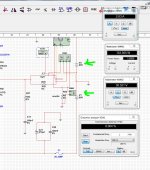
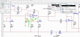
Well with the virtual prove from NI Multisim 13
I got from Q10 emitter -59.4V @ 3.54 mA from a 64V supply voltage,
with 90V supply I got from Q10 emitter -84.2V @ 3.89 mA
so that means that VAS Q10 is sending more current to drive Q9 a bit more BIAS ?
Juan
I got from Q10 emitter -59.4V @ 3.54 mA from a 64V supply voltage,
with 90V supply I got from Q10 emitter -84.2V @ 3.89 mA
so that means that VAS Q10 is sending more current to drive Q9 a bit more BIAS ?
Juan
Attachments
Can you simulate split supplies, run vas @90v reg supply and outputs at 64v...
uhmm ... let see what I can do I didn't think about that
Regards
Juan
We always knew the vas would benefit from more voltage than what was being used, this was discussed in the early days of the MK3, at the time i wanted split rails to run the outputs at 45v ...
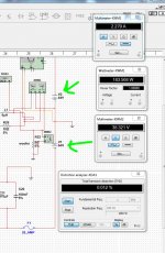
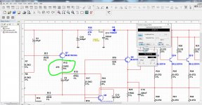
I check with different supply voltage as you mention but no changes, so I pinch somewhere in R12 and increase from 470ohms to 1k5 and now with 64V supply THD is low 0.004% the reason I'm doing this is in case I do not have a toroid transformer with 65V 0 65V I can then use 45V 0 45, this simulation is with 1KHz sine wave 500mVp input to 8 ohms load
Regards
Juan
Attachments
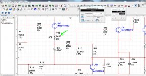
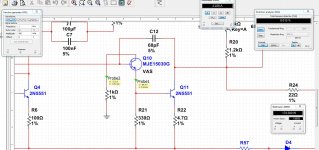
for thr two set ups you have
64V > -4.6V drop, across the VAS Vce
90V > -5.8V drop, further from the supply rail = higher Vce.
Do the same for the +ve side and compare.
Taking the VAS very close to the supply rails will increase the distortion.
Conversely, using a smaller section of the available VAS voltage swing will reduce the distortion.
for thr two set ups you have
64V > -4.6V drop, across the VAS Vce
90V > -5.8V drop, further from the supply rail = higher Vce.
Do the same for the +ve side and compare.
Taking the VAS very close to the supply rails will increase the distortion.
Conversely, using a smaller section of the available VAS voltage swing will reduce the distortion.
I will see how is going to react today
Regards
Juan
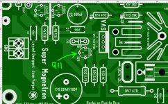
Q7 should be replaced with jumper between C-E, not simply removed, and than remove R11, too . It is basic misunderstanding about principles of circuit function..And You have to swap Q11 and Q10. R12, R15 must be minimum 6W (better 10w) resistors, for +-90V is dissipation 4,3W for each (if value is 470R), also Pc for VAS transistor will be near 9W!!I removed and the circuit stop working
But how is this possible, if
??No modifications allowed to this design...already made
It is not possible to develop amplifier only with simulations .
Last edited:
- Status
- Not open for further replies.
- Home
- Amplifiers
- Solid State
- Dx Blame MKIII-Hx - Builder's thread