R17 is not a signal current. Connect it to the Power Ground (the other end of R31).
If the Q7 is passing the correct current (~1mA) then R17 will also pass ~1mA.
It should drop ~1V
P = IV = 1*0.001 = 1mW
It can't burn out.
It is there to prevent Q7 burning out.
Hi Drew,
Thanks for the info....
Hi Willy-
I made this mod also and had no problem with R17. It doesn't make sense that moving that end of R17 from the lifted signal ground to main ground could cause the problem. You are only reducing the resistance from collector to ground by 10 ohms (1%). I think you must have a wiring error or short somewhere. Are you sure you cut the correct trace?
Steve
Hi Steve,
Yes I’m pretty sure I cut the correct trace, anyway let me try once more tonight I might miss somewhere that causing this error….
Thanks Steve.
Regards,
Willy
Hi Terry,
I tried to follow your mod last night but R17 (1K) burns out...
Please clarify did you really include R17 to the main ground??
I'm confuse between these two mods of you and martin on post 2015 as he keep the R17 on the lifted ground.
Regards,
Willy
I looked back and I see that I connected R17 to main ground.
http://www.diyaudio.com/forums/soli...-mkiii-hx-builders-thread-41.html#post3761094
I looked back and I see that I connected R17 to main ground.
http://www.diyaudio.com/forums/soli...-mkiii-hx-builders-thread-41.html#post3761094
Mods applied and it works now, Thanks Terry...
Attachments
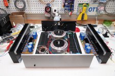
Hello guys 
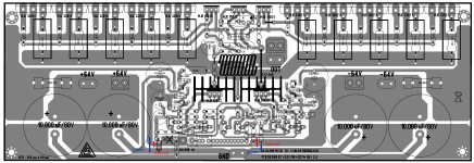
This is a bit crazy what I'm doing right now but I will post it any way, this is an old layout I did last year and I never have the change to try out is basically Dx Blame MKIII same circuit that Carlos design already I just want it to try different style layout.
What I have in mind about the layout is the distance between main power transistors so this might change later on, also the fuses I also have to relocate them too, any way this is my project to have fun.
Regards
Juan
This is a bit crazy what I'm doing right now but I will post it any way, this is an old layout I did last year and I never have the change to try out is basically Dx Blame MKIII same circuit that Carlos design already I just want it to try different style layout.
What I have in mind about the layout is the distance between main power transistors so this might change later on, also the fuses I also have to relocate them too, any way this is my project to have fun
.Regards
Juan
Attachments
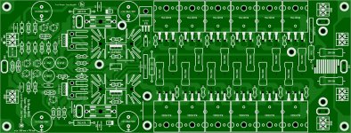
I see on this layout that the only thing on the lifted ground is the input itself. I also notice that the ground runs continuous around the entire board. I see like 5 different locations for attaching to ground. I don't know a lot about it but since I had trouble getting rid of ground hum issues on my boards I look for that. It will be interesting to see if this ground scheme fixes it.
Blessings, Terry
Blessings, Terry
I see on this layout that the only thing on the lifted ground is the input itself. I also notice that the ground runs continuous around the entire board. I see like 5 different locations for attaching to ground. I don't know a lot about it but since I had trouble getting rid of ground hum issues on my boards I look for that. It will be interesting to see if this ground scheme fixes it.
Blessings, Terry
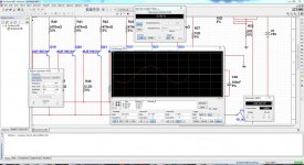
Hi Terry well the design from mister Carlos I simulated many times and respond really well I fallow all tips and I have been going back and forward reading all changes I still using Carlos schematic as always the only thing I did is add one more pair and also I increase the voltage a bit 75V supply.
Juan
Attachments
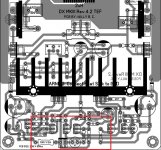
Hi Terry,
If I turn this resistance 8k2 as shown on picture and cut the tracers and make the 2 jumpers then it is good?
I'm asking just for the security so I make no error.
Tomorrow I make this modification, and hear if the hum is away
Regards,
Rudy
If I turn this resistance 8k2 as shown on picture and cut the tracers and make the 2 jumpers then it is good?
I'm asking just for the security so I make no error.
Tomorrow I make this modification, and hear if the hum is away
Regards,
Rudy
Attachments
Last edited:
oh ok, I will that out now
Juan
Hi Rudy,
Yes, that is exactly what I did. That makes the PCB match the schematic. I still have a very slight hum but it is very slight. Not noticeable unless you are very close to the speaker.
Hi Juan,
You say you have no hum. Is you amp mounted in a case with earth ground attached? Mine didn't hum until I put it in a case. Even then it didn't hum without something attached to the input. It took the modifications that Rudy is showing to get rid of it. As I said, with those mods, it matches the schematic.
Blessings, Terry
Hi Rudy,
Yes, that is exactly what I did. That makes the PCB match the schematic. I still have a very slight hum but it is very slight. Not noticeable unless you are very close to the speaker.
Hi Juan,
You say you have no hum. Is you amp mounted in a case with earth ground attached? Mine didn't hum until I put it in a case. Even then it didn't hum without something attached to the input. It took the modifications that Rudy is showing to get rid of it. As I said, with those mods, it matches the schematic.
Blessings, Terry
I never has the chance to have it in a chassis yet, probably is because the magnetic waves from the toroid transformer or earth problems affect yours, did you rated the toroid ? I read a long time ago that on building amps the toroid has to rated to specific way to keep magnet waves to it lowest level possible.
Juan
Hi Juan,
Put yours in a case with earth ground and then let us know if you still have no hum. Mine was fine spread out on the bench.
Sadly I do not have a chassis case yet but if in the future I have one I let you know if hum come out after chassis install
Juan
- Status
- Not open for further replies.
- Home
- Amplifiers
- Solid State
- Dx Blame MKIII-Hx - Builder's thread