Greetings to all.
My name is Marian, i'm new here and I'm sorry to bother you with this but i'm kind of desperate, i have a problem with an EV 7300A power amplifier and i'm in great need of help.
The problem is with channel 1 with is silent, the protection LED on the front pannel stays on permanently, so the power amp inside is closed, this would seam to be cuse of some DC ofset voltage at the output that i have found but i cannot find the reason why it is, i have removed all the power transistors and checked them out and they all are ok, as are the other transistors on the board, then i have checked the other active components ( diodes, zenners ) and they are ok as well, i did found R31 to be foulty ( interupted ) and replaced it, and the power on LED on the board CR21 shorted out, i've replaced it either, now as i was nosing around i found what it first seam to be the the problem with OP Amp NE5532, i found a big difference of voltage between the rails at it's pins, as the negative one was ok at -15Vdc, the possitive one oscilating around +5Vdc, since all other components seam to be ok i have removed the OP and with it removed the voltage rails returned to good working size, +/-15Vdc, then i replaced the OP with a new one but the problem did not go away, i have put the old OP on the working module and it is ok there, but here every time i put the IC in the socket the possitive rail goes down allot, throug thoroughly verification i have found that the main positive rail goes down in fact ( that is measured against the ground ) so i have changed the power line with the one from the working module but still the same, with the NE5532 in it's socket the main positive voltage rail goes way down at a slow but steady rate, that i cannot understand why, i have also found an strange ( to me that is ) voltage difference between the power lines of the modules, i mean that as the working one has a +78/-53 Vdc the foulty one has +59/-72Vdc, i also verified most of the capacitors, searched for blown or defective resistors and came up empty..
Now i came here to you askin for help of any kind, i realy need to solve this amp as it's one of my best friend's amp, so any help is greatly appreciated.
Here is the link to the manual http://archives.telex.com/archives/EV/Amplifiers/Owners%20Manual/7300A%20Owners%20Manual.pdf, and thank you all for your time.
Marian.
Output transistors "okay" is a touchy subject if you have DC on the speaker output line. I found doing the double diode test on BJT O.T's of a blown amp, that some were open, some shorted, some fine, and some a little weird. Fine is, on my meter, about 600 ohm on the 2000 ohm scale forward and 1 megohm or better backwards. My meter doesn't see any resistance forward on the 200 ohm scale, depends on the battery voltage what they do. The weird O.T.'s were 400 ohm forwards. I replaced them.
Get a good transistor of any BJT kind, or a diode, and see what your meter reads forward on a junction. Then the the "good" transistors should read that forward, not 2/3 of that.
Another way to test which transistors are putting out DC is to remove all but one upper rail and one lower rail output transistor (if you have multiple pairs). Then power on. No DC- those two are okay. If you can't find any pair of O.T.'s that don't produce DC, go buy some.
Pulling the wire from the drivers to the base of the O.T's may be necessary. O'T's should sit there with nothing connected to the base, except a disc capacitor to emmiter, holding off DC, as long as you aren't injecting RF with a cell phone or something.
Also check if you have a protection circuit in parallel with the output transistors, that is also blown up. Like, my PV1.3k had a triac on the output, that was also shorted. One of the two diac's (bidirectional switch) also.
A link to the schematic on the internet, or an upload of the one you have, would allow more detailed analysis of symptoms like "r31 shorted". People that run shops don't waste a lot of money-making time here, although some shop owners do drop in occasionally when they get tired of talking to customers.
Last edited:
SInce fuses are not blowing, I am willing to believe the outputs are not shorted.
Indiana, he did link to the schematic in post #1.
This amp is reminiscent of QSC circuits. If the +/-15v is OK without the IC, but the one side falls when it is in, then look at the main power rails. Are they seriously out of balance? In other words, are the main power rails instead of something like 80 and 80, more like 40 and 120? The 15v rails derive from the high voltage rails.
Enzo is a shop owner, you have had one of the forum expert's opinion.
I read the explanation on here of the tricky way QSC makes their speaker ground, and decided not to buy one, especially not a dead one . I'd have to buy Bob Cordell's book to understand it, I think. If the speaker ground is not in the middle of the supply rails, no wonder.
I read the explanation on here of the tricky way QSC makes their speaker ground, and decided not to buy one, especially not a dead one . I'd have to buy Bob Cordell's book to understand it, I think. If the speaker ground is not in the middle of the supply rails, no wonder.
Last edited:
Greetings to all.
As i sayd before, the power transistors are ok, i have removed and checked each and every one of them, and trust me i know a good transistor when i see one.
Nothing is blown up, i did checked carefully for that, and the component seams to be ok and that is my dilema.
I did posted a link to the owners manual in PDF format, sorry if you missed it, check it and you will understand what i am talking about.
The main power lines are like this:
->The 2 outputs of the power transformer are both the same at 100Vac.
->As for the DC power lines on the board, well each module has a separate power line so the good module has a +78/-53Vdc power, the foulty one has +59/-72, so there is an important difference between the rails, ( i will not comment it cus i did not worked with this cind of ground before and i do not understand it best ), but strange ( for me ) is that on the working module the negative rail is the smaller one, but in the other one it is the oposite, the positive one is the smaller one, if i swithc between them, if i put the line from the good module on the foulty one nothing changes, and if i conect the one from the defective module on to the good one it works just fine, so the main power lines must be ok both of them but still... they do not work the same and that is one other thing i cannot understand why..?.
It would seam to be a problem with the ground circuit, but this is where i am stumbling cus i cannot understand this cind of ground, i did not worked with it before now and despite of my intensive search on the net i did not find anything to clear my mind about it, the ground circuit does not seam to come from anywhere in particular but still it has great power, so can you help me understand it at least a bit?..
Output transistors "okay" is a touchy subject if you have DC on the speaker output line. I found doing the double diode test on BJT O.T's of a blown amp, that some were open, some shorted, some fine, and some a little weird. Fine is, on my meter, about 600 ohm on the 2000 ohm scale forward and 1 megohm or better backwards. My meter doesn't see any resistance forward on the 200 ohm scale, depends on the battery voltage what they do. The weird O.T.'s were 400 ohm forwards. I replaced them.
Get a good transistor of any BJT kind, or a diode, and see what your meter reads forward on a junction. Then the the "good" transistors should read that forward, not 2/3 of that.
Another way to test which transistors are putting out DC is to remove all but one upper rail and one lower rail output transistor (if you have multiple pairs). Then power on. No DC- those two are okay. If you can't find any pair of O.T.'s that don't produce DC, go buy some.
Pulling the wire from the drivers to the base of the O.T's may be necessary. O'T's should sit there with nothing connected to the base, except a disc capacitor to emmiter, holding off DC, as long as you aren't injecting RF with a cell phone or something.
Also check if you have a protection circuit in parallel with the output transistors, that is also blown up. Like, my PV1.3k had a triac on the output, that was also shorted. One of the two diac's (bidirectional switch) also.
A link to the schematic on the internet, or an upload of the one you have, would allow more detailed analysis of symptoms like "r31 shorted". People that run shops don't waste a lot of money-making time here, although some shop owners do drop in occasionally when they get tired of talking to customers.
As i sayd before, the power transistors are ok, i have removed and checked each and every one of them, and trust me i know a good transistor when i see one.
Nothing is blown up, i did checked carefully for that, and the component seams to be ok and that is my dilema.
I did posted a link to the owners manual in PDF format, sorry if you missed it, check it and you will understand what i am talking about.
SInce fuses are not blowing, I am willing to believe the outputs are not shorted.
Indiana, he did link to the schematic in post #1.
This amp is reminiscent of QSC circuits. If the +/-15v is OK without the IC, but the one side falls when it is in, then look at the main power rails. Are they seriously out of balance? In other words, are the main power rails instead of something like 80 and 80, more like 40 and 120? The 15v rails derive from the high voltage rails.
The main power lines are like this:
->The 2 outputs of the power transformer are both the same at 100Vac.
->As for the DC power lines on the board, well each module has a separate power line so the good module has a +78/-53Vdc power, the foulty one has +59/-72, so there is an important difference between the rails, ( i will not comment it cus i did not worked with this cind of ground before and i do not understand it best ), but strange ( for me ) is that on the working module the negative rail is the smaller one, but in the other one it is the oposite, the positive one is the smaller one, if i swithc between them, if i put the line from the good module on the foulty one nothing changes, and if i conect the one from the defective module on to the good one it works just fine, so the main power lines must be ok both of them but still... they do not work the same and that is one other thing i cannot understand why..?.
It would seam to be a problem with the ground circuit, but this is where i am stumbling cus i cannot understand this cind of ground, i did not worked with it before now and despite of my intensive search on the net i did not find anything to clear my mind about it, the ground circuit does not seam to come from anywhere in particular but still it has great power, so can you help me understand it at least a bit?..
Hi MarianB,
It would be nice if they included the information on the protection / bias PCB.
So, you're really only misguided due to using the same name for more than two circuit nodes. When is "ground", not a ground? When it's the common between the filter caps as this point connects to the common point through the loudspeaker. It works the same as most other amps with this wrinkle and the two high current floating power supplies.
Let's clear a couple things up first. I'll assume your meter common point is the input common (ground) at some point. You are measuring floating supplies from that perspective. If you were to measure from the speaker positive terminal to each supply capacitor terminal, you would see close to the same voltages on each. We're talking about the absolute value with polarity ignored of course.
You tested the power transistors (plus maybe others) and declared them to be good. So how exactly did you test them? Were you able to measure beta and leakage (in uA) for collector - base and collector - emitter? If not, you have not tested your output transistors properly. You may still have a defect. Swapping parts from one channel to the other should never, ever be done. That's a great way to end up with two dead channels instead of one and still have no clue what parts may be defective. Please do not do that ever again. It's a really bad habit.
Neither channel readings are good. Your reference point is in the wrong place for these measurements. What you should be noticing is that both supplies have similar, but opposite offsets (they are pretty close for how this circuit is designed and where the reference for the meter is). Simply deciding that one is correct is an error in logic since they both show an offset from having the same reading for positive and negative supplies.
Enzo made an excellent suggestion on how to check the op amps. Let's add to that. On each op amp, measure pins 2 and 3, then pin 1. Measure pins 5 and 6, then pin 7 and record the readings. Op amps "want" to make the two inputs (2,3 and 5,6) equal in voltage. So there should only be low mV between each of the two inputs (allowing for meter errors). I'm talking about each section, not comparing between both sections. Look at the output DC voltages on the output pins (1 and 7) to see if they are in the linear range of operation, or pegged to one rail or the other. From there, you can follow the schematic to determine where the fault probably is. Please let us know what you come up with.
One thing will probably really help you do some troubleshooting. On a piece of paper, write down only your observations and measurements. Do not write down any conclusions at all. Once you have made the measurements you wanted, and inspected the unit visually, sit down and have a look at your observations and the schematic. Then, write down any ideas you may have on another piece of paper. Always keep your observations separated from any conclusions or ideas you may have. I can see that this is tripping you up already.
-Chris
It would be nice if they included the information on the protection / bias PCB.
So, you're really only misguided due to using the same name for more than two circuit nodes. When is "ground", not a ground? When it's the common between the filter caps as this point connects to the common point through the loudspeaker. It works the same as most other amps with this wrinkle and the two high current floating power supplies.
Let's clear a couple things up first. I'll assume your meter common point is the input common (ground) at some point. You are measuring floating supplies from that perspective. If you were to measure from the speaker positive terminal to each supply capacitor terminal, you would see close to the same voltages on each. We're talking about the absolute value with polarity ignored of course.
Sorry, no. I don't buy that statement without knowing you.As i sayd before, the power transistors are ok, i have removed and checked each and every one of them, and trust me i know a good transistor when i see one.
You tested the power transistors (plus maybe others) and declared them to be good. So how exactly did you test them? Were you able to measure beta and leakage (in uA) for collector - base and collector - emitter? If not, you have not tested your output transistors properly. You may still have a defect. Swapping parts from one channel to the other should never, ever be done. That's a great way to end up with two dead channels instead of one and still have no clue what parts may be defective. Please do not do that ever again. It's a really bad habit.
Again, no. We know something is bad. A damaged component does not have to be totally open or shorted to be defective. At this point we do know that either one or more parts are bad, or you have a problem on a circuit board or maybe even a short or leakage on the PCB itself. Did anything get spilled inside?Nothing is blown up, i did checked carefully for that, and the component seams to be ok and that is my dilema.
Nope.As for the DC power lines on the board, well each module has a separate power line so the good module has a +78/-53Vdc power, the foulty one has +59/-72, so there is an important difference between the rails,
Neither channel readings are good. Your reference point is in the wrong place for these measurements. What you should be noticing is that both supplies have similar, but opposite offsets (they are pretty close for how this circuit is designed and where the reference for the meter is). Simply deciding that one is correct is an error in logic since they both show an offset from having the same reading for positive and negative supplies.
Enzo made an excellent suggestion on how to check the op amps. Let's add to that. On each op amp, measure pins 2 and 3, then pin 1. Measure pins 5 and 6, then pin 7 and record the readings. Op amps "want" to make the two inputs (2,3 and 5,6) equal in voltage. So there should only be low mV between each of the two inputs (allowing for meter errors). I'm talking about each section, not comparing between both sections. Look at the output DC voltages on the output pins (1 and 7) to see if they are in the linear range of operation, or pegged to one rail or the other. From there, you can follow the schematic to determine where the fault probably is. Please let us know what you come up with.
One thing will probably really help you do some troubleshooting. On a piece of paper, write down only your observations and measurements. Do not write down any conclusions at all. Once you have made the measurements you wanted, and inspected the unit visually, sit down and have a look at your observations and the schematic. Then, write down any ideas you may have on another piece of paper. Always keep your observations separated from any conclusions or ideas you may have. I can see that this is tripping you up already.
-Chris
So, you're really only misguided due to using the same name for more than two circuit nodes. When is "ground", not a ground? When it's the common between the filter caps as this point connects to the common point through the loudspeaker. It works the same as most other amps with this wrinkle and the two high current floating power supplies.
This is how i understand the concept of ground on a symmetrical power supply, it is the middle point on the power transformer's secondary winding, and at the same time the common point between the filter capacitors, that i understand to be the most tipes of ground used, the concept of floating ground to me would be something like that on the ATX power supplyes, but here it does not seam to be the case as that common point leads in fact to te positive output of the speaker, i appologise for my ignorance but as i sayd i did not worked with this configuration before, and i still do not understand from where does the ground on the board get's it's power, i did saw at the star ground screw on the case 2 ceramic capacitors that lead to the main power lines ( 220 ) but i do not think that is it's source of power.
Let's clear a couple things up first. I'll assume your meter common point is the input common (ground) at some point. You are measuring floating supplies from that perspective. If you were to measure from the speaker positive terminal to each supply capacitor terminal, you would see close to the same voltages on each. We're talking about the absolute value with polarity ignored of course.
I used as my meter common point the big ground circuit, the one that is connected to the negative terminal of the loudspeaker and at the same time to the case of the power transistor, that was my reference point as with all the other amps i have worked with before, but i'l do as you say, i'll check the voltages on the caps terminals.
Sorry, no. I don't buy that statement without knowing you.
You tested the power transistors (plus maybe others) and declared them to be good. So how exactly did you test them? Were you able to measure beta and leakage (in uA) for collector - base and collector - emitter? If not, you have not tested your output transistors properly. You may still have a defect. Swapping parts from one channel to the other should never, ever be done. That's a great way to end up with two dead channels instead of one and still have no clue what parts may be defective. Please do not do that ever again. It's a really bad habit.
I will not state that i'm some cind of expert on measuring the transistors, but still i am not a begginer either, i do have a digital multitester and i do measure it's beta factor as well as it's diode conection, and that is why i sayd that they are good, ok you do not trust me, i can accept that it's true we do not know each other, but still i would not have come here on this most respectable forum if i did not know at least that, but still i will check them again as you say and compare the results with theyr PDF's.
As for Swapping parts, well i do know it is not a good thing to do, what i did change i did it after checking to make sure i would not harm the other one as best i could, but i will keep in mind youre advice.
Again, no. We know something is bad. A damaged component does not have to be totally open or shorted to be defective. At this point we do know that either one or more parts are bad, or you have a problem on a circuit board or maybe even a short or leakage on the PCB itself. Did anything get spilled inside?
Ok, maybe i overestimated my observations and i appologise, it is obvious something is bad since it's not working, i did check the board for circuit foult or short somewhere but i did not found any, and the owner did not say much about the reason for the amp malfunction or how it happened, he just sayd something like yesterday was working fine and today it did not.. he did say that he used the amp on bridge config for some time, now as i took a first lok inside i did not found any evidence that something was spilled on it, it loked clean but the thin is i am not the first one that tried to troubleshoot the amp, the other guy did not say much to the owner, just that he can't fixe it so i cannot be sure of anything, but i did found problems, as i sayd R31 was open, ( the one that reads the output of the speaker for the protection circuit ), and the power on LED on the board shorted, and another thing, i found some cold solderings on a coupple of power transistors, now i do not know if that could have caused some cind of chain reaction, i checked then all the soldering and fixed all that seamed not to be ok.
Neither channel readings are good. Your reference point is in the wrong place for these measurements. What you should be noticing is that both supplies have similar, but opposite offsets (they are pretty close for how this circuit is designed and where the reference for the meter is). Simply deciding that one is correct is an error in logic since they both show an offset from having the same reading for positive and negative supplies.
Ok i was wrong it seams, maybe the reference point it is not well chosen, and i will check as i sayd on the caps terminal and see, but i was wright that the offset is opposite from one channel to the other and that i cannot understand why.
Enzo made an excellent suggestion on how to check the op amps. Let's add to that. On each op amp, measure pins 2 and 3, then pin 1. Measure pins 5 and 6, then pin 7 and record the readings. Op amps "want" to make the two inputs (2,3 and 5,6) equal in voltage. So there should only be low mV between each of the two inputs (allowing for meter errors). I'm talking about each section, not comparing between both sections. Look at the output DC voltages on the output pins (1 and 7) to see if they are in the linear range of operation, or pegged to one rail or the other. From there, you can follow the schematic to determine where the fault probably is. Please let us know what you come up with.
The Op amps themselfs must be ok since both of them work fine on the good channel, but i will check them as you sugested and see what goes around there, sadly i do not have acces to an scope as i am sure the problem would be much easyer to find.
Now, i apologise for such long message, but i had to give as much detailes as i could, and i must thank you sincerely for your time and youre much apreciated imput, it helps me allot, so many thanks to you all for youre patience, and i wish you all the best.
Marian.
I will suggest that you listen the Anatech.
This is not really a difficult amplifier. It is the for runner to the EV2400 and 3200 if my memory is correct. Have had a few on my bench in the last 20yrs.
The Altec 9442 and 9444 share the same basic circuit.
I would suggest that you re-measure the power supply.
Do not assume that the outputs are good unless you have checked them with a good VOM meter and or a good transistor tester. I use a transistor tester or a test circuit in which to test my transistors.
I could put a quick end to the problem here by opening up my notebook that I have kept notes on various problems associated with the EV's and Altecs but I will prefer to let this thread ride out so that you will have a chance to learn and be able to appreciate the help and understanding that is available from fellow members here.
Last edited:
I will suggest that you listen the Anatech.
This is not really a difficult amplifier. It is the for runner to the EV2400 and 3200 if my memory is correct. Have had a few on my bench in the last 20yrs.
The Altec 9442 and 9444 share the same basic circuit.
I would suggest that you re-measure the power supply.
Do not assume that the outputs are good unless you have checked them with a good VOM meter and or a good transistor tester. I use a transistor tester or a test circuit in which to test my transistors.
I could put a quick end to the problem here by opening up my notebook that I have kept notes on various problems associated with the EV's and Altecs but I will prefer to let this thread ride out so that you will have a chance to learn and be able to appreciate the help and understanding that is available from fellow members here.
Correct me if i am wrong but as i see it you sort of acuse me of some things like:
1.Not listening to Anatech or ignoring he's imput.
2.Not knowing something so simple like measuring voltage and current. ( simple to me that is ).
3.Not knowing how to discern a good transistor from a bad one.
4.And finaly not appreciating the help and imput from this forum.
Now please i beg of you not to missunderstand me, i give you my word i'm not trying to be rude, but i have to know, when did i du those thing you acuse me of? when or how did i ignore Anatech? have i sayd something that made u understand i did not appreciate the help? or that i don't care of anything you all say?
Again i hope you don't take me wrong, i swear i have only the best intentions here, i'm not trying or intending to upset anyone, i'm just trying to fix my problem, and as i sayd before i will do exactly as Anatech sayd i should.
Hi,
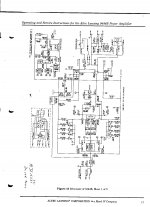
At the beginning of the tread you mentioned that the +15 volts at the NE5532 is reading +5. Also you said that you replaced it with a new one with the same results. If you check the protection circuit pin marked A also feed both the NE5532 and the protection circuit thru a diode. I can not read the diode number "CR26" but one of the test you can do is lift one side of the diode and see if the voltage at the NE5532 read good +15. This will isolate the NE5532 +15 volts. It is possible the Q21 or the diode is bad.
At the beginning of the tread you mentioned that the +15 volts at the NE5532 is reading +5. Also you said that you replaced it with a new one with the same results. If you check the protection circuit pin marked A also feed both the NE5532 and the protection circuit thru a diode. I can not read the diode number "CR26" but one of the test you can do is lift one side of the diode and see if the voltage at the NE5532 read good +15. This will isolate the NE5532 +15 volts. It is possible the Q21 or the diode is bad.
quote:
Correct me if i am wrong but as i see it you sort of acuse me of some things like:
1.Not listening to Anatech or ignoring he's imput.
2.Not knowing something so simple like measuring voltage and current. ( simple to me that is ).
3.Not knowing how to discern a good transistor from a bad one.
4.And finaly not appreciating the help and imput from this forum.
yes, you are correct. When you become more willing to listen then something will be accomplished in my opinion. My suggestion is instead of taking offense to something stand back and listen. Anatech is one of the best here when it comes to figuring out how something works and how to repair it. My suggestion is listen and learn.
Hi 6BG6A,
Well, thank you very much! But, how can I live up to a buildup like that?
I'm just a guy who suffered a lot in my past life as a tech. Much like many others here.
-Chris
Edit: I almost forgot to ask you .... Do you have a schematic that is more clear than the one attached in the first post? That would really help me out in this.
BTW, you probably have more experience repairing these than I do. You are more than welcome to point the way. I can only approach this from a general sense. Now, if it were on my bench in front of me, I'd remember more stuff. With this, you are the expert.
Last edited:
Hi MarianB,
No worries, we are fine. I just wanted to set the stage for a clear path where everyone here has a good idea of the progress. My cautions are to help you out and prevent further damage that add to your list of troubles. Often another fault can be created that doesn't have a cause and effect trail. I call those "panicking technician syndrome".
Have you heard of T.I.M.? That stands for Technician Induced Malfunction. Most technicians have been called on to repair units suffering from a previous repair attempt. They are not fun and are often "unrepairable", or B.E.R. (Beyond Economic Repair). Now that we have the acronyms out of the way ...
This design allows the transistor cases to be connected to the heat sink without using transistor insulators. It buys them a little extra cooling ability. In this case, they move the speaker connections between the signal / chassis common (ground) and the common point between the main power supply filter capacitors and float these power supplies. It ends up doing the same thing the normal construction does. With a normal amplifier, the speaker ends up being between the amplifier output (normally positive speaker terminal) and the power supply common (speaker negative terminal) which also happens to be connected to the signal common (ground). The energy flows from the positive supply, through the speaker and to the capacitor common, then a similar route for the negative on the next half cycle. The amp you are working on does the same thing, except that the speaker positive connects to the "grounded" outputs and then to the power supply common. You still have energy flow from the business end of a filter capacitor and around to it's common terminal. It's a series circuit, and they moved the speaker connection - that's all. The amplifier works the same as a normal one does on a basic level. It's just that you are not familiar with how the amp is set up. It does drive home the point that the power supply is in series with the speaker output though! Reference your meter to the chassis or signal common (ground) point. Things will make more sense, but beware that you can not make your normal assumptions. Coffee is your friend.
When measuring the filter capacitors, just make sure you measure them across their actual terminals. Then you know exactly what you are measuring. Remember, no assumptions any more.
I'm not sure how you resolder connections, but on older equipment you should remove the solder, scrape - clean the component leads affected, then add some liquid (electronic) solder flux and redo the connections. Don't use too much solder and avoid lead-free solder and no-clean flux. Some of that stuff can turn conductive. For thermal paste, do not use the stuff for computer CPUs. It may also be conductive!
Now, did you confirm that all the parts in the amp are original to the amp? If the amp has been serviced before, are the parts the original numbers, or at least proper substitutes. If any parts are marked "ECG" or "NTE" (any replacement brand), they need to be replaced with the correct parts. I am not joking about this. Replacement brand semiconductors are terrible. They are also going to be different than the proper part(s).
Your details are welcome, and going through while measuring voltages and resistances is a good start. Begin as if it's the very first time you have opened this amplifier. Assume nothing.
I hope you find something quickly just so you can get through this.
Best, Chris
No worries, we are fine. I just wanted to set the stage for a clear path where everyone here has a good idea of the progress. My cautions are to help you out and prevent further damage that add to your list of troubles. Often another fault can be created that doesn't have a cause and effect trail. I call those "panicking technician syndrome".
Have you heard of T.I.M.? That stands for Technician Induced Malfunction. Most technicians have been called on to repair units suffering from a previous repair attempt. They are not fun and are often "unrepairable", or B.E.R. (Beyond Economic Repair). Now that we have the acronyms out of the way ...
This design allows the transistor cases to be connected to the heat sink without using transistor insulators. It buys them a little extra cooling ability. In this case, they move the speaker connections between the signal / chassis common (ground) and the common point between the main power supply filter capacitors and float these power supplies. It ends up doing the same thing the normal construction does. With a normal amplifier, the speaker ends up being between the amplifier output (normally positive speaker terminal) and the power supply common (speaker negative terminal) which also happens to be connected to the signal common (ground). The energy flows from the positive supply, through the speaker and to the capacitor common, then a similar route for the negative on the next half cycle. The amp you are working on does the same thing, except that the speaker positive connects to the "grounded" outputs and then to the power supply common. You still have energy flow from the business end of a filter capacitor and around to it's common terminal. It's a series circuit, and they moved the speaker connection - that's all. The amplifier works the same as a normal one does on a basic level. It's just that you are not familiar with how the amp is set up. It does drive home the point that the power supply is in series with the speaker output though! Reference your meter to the chassis or signal common (ground) point. Things will make more sense, but beware that you can not make your normal assumptions. Coffee is your friend.
When measuring the filter capacitors, just make sure you measure them across their actual terminals. Then you know exactly what you are measuring. Remember, no assumptions any more.
Marian, this is your first assumption. Testing the transistors this way and assuming that all defects will show up. The best test is a curve tracer, properly set up. The next best is a jig you make and set the transistors up as they would be in an amplifier, then measure each base current and emitter current to figure out the beta. Turn the transistors all off and then measure leakage current in the uA. What you did will catch massive faults, but not the small ones that can blow up an amplifier. I find the leakage test catches many transistors that look good otherwise. One excellent service meter was made by Heathkit, called the IT-18 transistor tester. There are other similar models and brands, just make sure they actually measure beta, C-E leakage directly and C-B leakage directly. One more thing. When the amplifier is idling, you want to make sure the current is shared equally between the like output transistors. At higher currents, the emitter resistors will force current sharing. Also, an open emitter resistor may measure an expected voltage drop. Measure the darn things directly - no assumptions.I will not state that i'm some cind of expert on measuring the transistors, but still i am not a begginer either, i do have a digital multitester and i do measure it's beta factor as well as it's diode conection
Don't worry about this. Good techs only get stuck on simple problems. It's true. Ask anyone who has experience, and they'll tell you that it's the silly things they overlooked that got them stuck. That's just life. Maybe a little Karma in there as well.Ok, maybe i overestimated my observations and i appologise,
That's using your eyes. Where there are a few bad solder connections, there are bound to be many more. Was this amplifier on the road for any length of time? Redo any solder connections between heavy components and solid parts and the PCB. You may not be able to see them all.i found some cold solderings on a coupple of power transistors, now i do not know if that could have caused some cind of chain reaction, i checked then all the soldering and fixed all that seamed not to be ok.
I'm not sure how you resolder connections, but on older equipment you should remove the solder, scrape - clean the component leads affected, then add some liquid (electronic) solder flux and redo the connections. Don't use too much solder and avoid lead-free solder and no-clean flux. Some of that stuff can turn conductive. For thermal paste, do not use the stuff for computer CPUs. It may also be conductive!
Yes you were. However you did assume the working channel were the correct readings. That was not correct. Anyway, ignore that for the moment and concentrate on eliminating problem components and solder connections.i was wright that the offset is opposite from one channel to the other and that i cannot understand why.
Now, did you confirm that all the parts in the amp are original to the amp? If the amp has been serviced before, are the parts the original numbers, or at least proper substitutes. If any parts are marked "ECG" or "NTE" (any replacement brand), they need to be replaced with the correct parts. I am not joking about this. Replacement brand semiconductors are terrible. They are also going to be different than the proper part(s).
Your details are welcome, and going through while measuring voltages and resistances is a good start. Begin as if it's the very first time you have opened this amplifier. Assume nothing.
I hope you find something quickly just so you can get through this.
Best, Chris
Hate to say this people but I do believe the schematic might be incorrect. I thought the schematic looked familiar and it is. The schematic is 100% that of an Altec 9444B amplifier and possibly not that of a 7300 EV.
I am looking at the Master Copy of a 7300 right now but not the 7300A version so I could be mistaken.
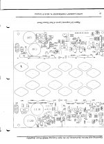
Right now it would be imperative that you compare the layout PB board wise to that as shown in the downloaded manual to see if they are the same before going further.
I am looking at the Master Copy of a 7300 right now but not the 7300A version so I could be mistaken.
Right now it would be imperative that you compare the layout PB board wise to that as shown in the downloaded manual to see if they are the same before going further.
Last edited:
The 7300's op amp drives 2 transistors on its output.
If the 7300A is different its op amp output does NOT drive the two transistors. Its output can be easily traceable to a diode bridge and a clip LED.
If the 7300A is the same animal as the 9444B then the board layout will be the same and the circuit will be the same.
Will try to upload 2) scans of the 9444B/9444B/SA to compare with your
7300A.
I do hope the 7300A is the same as the 9444B/9444B/SA If so please advise and I will distribute copies that can be easily read by the interested people here.
If this is a carbon copy of the 9444B then I will tell you that the protection circuit is a trouble maker in these particular amps and they are prone to problems associated with leaky and or defective caps in the protection circuit.
Attachments
Last edited:
quote:
Hi 6BG6A,
Well, thank you very much! But, how can I live up to a buildup like that?
I'm just a guy who suffered a lot in my past life as a tech. Much like many others here.
-Chris
Edit: I almost forgot to ask you .... Do you have a schematic that is more clear than the one attached in the first post? That would really help me out in this.
BTW, you probably have more experience repairing these than I do. You are more than welcome to point the way. I can only approach this from a general sense. Now, if it were on my bench in front of me, I'd remember more stuff. With this, you are the expert.
--------------------------------------------------------------------------------
Last edited by anatech; Yesterday at 08:22 PM. Reason: Further queries / comments for 6BG6A
Well Sir I am proud to walk in your shadow but cannot come close to your abilities.
I have posted some information. I am not sure at this point if the 7300A is the same as the manual that is on line. The 7300 for sure is a totally different animal. If the 7300A is the same as a 9444B 9444B/SA then I can share some information that might possibly help.
I happen to have a working 9444B on hand in my personal collection of amplifiers that I could open up so that we could compare voltage readings and operations of a known good working animal.
I think that this can end up to be one of the better informative threads and would be more than happy to assist if I can with you running point.
- Home
- Amplifiers
- Solid State
- ElectroVoice 7300A trouble