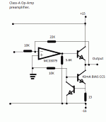
Here's a schematic I made and I'm about to construct the actual circuit.
It will be used as a part of a preamp for a diy sound system. I added an output stage to drive low impedance loads without bogging down the OpAmp. It will be driving a 560 ohm load (driving inverting input on power amp)
To preserve clarity, for my stereo L & R channels, and have less %THD, I want to do class-A preamp, with a good op-amp that has low THD as well.
Any opinions or tips, or questions about the circuit, feel free to post.
-Eworkshop1708
Attachments
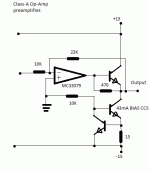
you'd have less AC load on the op amp output if you connected the bias R to the output Q emitter - the Vbe will be relatively constant and "bootstrap" the R to appear as a much higher impedance load to the op amp output - even after lowering the bias R value to give the desired current with the Vbe drop instead of the negative supply V
you'd have less AC load on the op amp output if you connected the bias R to the output Q emitter - the Vbe will be relatively constant and "bootstrap" the R to appear as a much higher impedance load to the op amp output - even after lowering the bias R value to give the desired current with the Vbe drop instead of the negative supply V
Interesting.........Thanks for the tip, I've made the change to the circuit.
I lowered the Class-A bias some on the OpAmp, but it should still remain in Class-A still because the 470 should still bypass enough current to keep the OpAmp biased on, even if the transistor is not loaded, because of the constant DC load from the CCS Class A output.
Attachments
Nice! I did somee work on a class A opamp based GP output stage a few months ago, and managed to get some measurements done on an AP. The results were really good, so I can vouch for this approach. You can read about my results here:-
Audio Amplifer Designhifisonix.com | hifisonix.com
see 'A Universal Small Signal Class A Buffer'
Good luck with your project")
Audio Amplifer Designhifisonix.com | hifisonix.com
see 'A Universal Small Signal Class A Buffer'
Good luck with your project
.
I lowered the Class-A bias some on the OpAmp, but it should still remain in Class-A still because the 470 should still bypass enough current to keep the OpAmp biased on, even if the transistor is not loaded, because of the constant DC load from the CCS Class A output.
Why not use a dedicated (and adjustable) CSS for the op-amp like in Bonsai's circuit, or this oldie from Walt Jung (Qn/D2/R?)?
http://waltjung.org/PDFs/WTnT_Op_Amp_Audio_2.pdf
(That is also a well performing op-amp buffer, able to run in class A. The four articles of the series are here:
Services )
I like the bootstrapped resistor (ClassA single ended opamp). I had not thought of that as a bootstrap, but seems so obvious when one is told.
The 470r draws ~1.2 to 1.4mA through the opamp. Will all opamps, those with high output bias and those with low output bias, perform similarly with that amount of single ended output current?
The 470r draws ~1.2 to 1.4mA through the opamp. Will all opamps, those with high output bias and those with low output bias, perform similarly with that amount of single ended output current?
some "audio" op amps appear to have ~ 100 uA output bias
some early generation DSL driver op amps may have a few mA - they were competing on MHz distortion specs - Scott Wurcer claims newer DSL chips are accepting a higher distortion number as adequate and trying to cut power dissipation
how "good" the Class A performance for a given bias can be easily calculated assuming op amp internal emitter follower and added buffer Q base current demand
I've used a very similar circuit for a headphone amp with great results. If you use a MOSFET for the pass element, the offset voltage on the gate means that the opamp output doesn't pass through zero until you get to larger signal levels, IMO a good feature if you can stand the slight loss of headroom. Heatsink the circuit well, bias it high enough, and you can even drive small speakers.
Reminds me of a circuit i simulated when a friend wanned to build a class A headphone amp, unfortunately he dident want the opamp and dual rails as it was not class A to him without the output coupling cap, so i never proceeded to actually building and testing it.
Heres my circuit with BJT's: http://i.imgur.com/Lk8Ql.png
With a mosfet: http://i.imgur.com/W0XLv.png
Heres my circuit with BJT's: http://i.imgur.com/Lk8Ql.png
With a mosfet: http://i.imgur.com/W0XLv.png
Whether class A AB or B, direct coupled (DC) is always better IMO. Especially when driving any kind of speaker. He should have been pleased with your attempt to make him a nice amp.
Big edit, I changed the post, LOL.........anyway.....
Being the Op-Amp is already spec'd for 0.002%THD, the Class A output should keep the trebles sounding real nice.
Would the Class-A Op-Amp with output stage be also good for driving subwoofer amps? I'm wondering if this would make any audible difference at just bass frequencies having more drive current, or would it be better to just parallel a couple opamps instead for more drive output and save the PCB space??
Last edited:
How much power will the transistors dissipate in this design? I've just built this with 2N3904s and they quickly get too hot to touch.
I actually only need to drive a 600ohm load right now, but I want to be sure I'm doing it without any kind of distortion, so I thought it'd be best to use this circuit instead of a straight op-amp. I'm trying to drive up to 20V-pp.
I can lower the bias current through the transistors by increasing the 15R resistor?
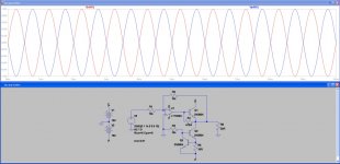
EDIT: Simulating, a value of 39Ohm can produce un-clipped output of nearly 22V-pp into 600Ohm loads. I'm trying it in the breadboard and the transistors seem happier, still hot, but probably within limits.
I actually only need to drive a 600ohm load right now, but I want to be sure I'm doing it without any kind of distortion, so I thought it'd be best to use this circuit instead of a straight op-amp. I'm trying to drive up to 20V-pp.
I can lower the bias current through the transistors by increasing the 15R resistor?
EDIT: Simulating, a value of 39Ohm can produce un-clipped output of nearly 22V-pp into 600Ohm loads. I'm trying it in the breadboard and the transistors seem happier, still hot, but probably within limits.
Last edited:
20Vpp into 600r will pass 16.7mApk through the load.
Using a push pull ClassA amplifier the output bias will need to be set to >8.4mA.
Let's set it to 10mA.
The device dissipation will be V * I.
for 20Vpp you need ~+-15Vdc supply rails.
This gives a dissipation of 150mW ~25% of Pmax, if Ta=25degC. This will run very warm.
Check what output bias current you are running.
BTW,
using Re~2r4 will allow optimum ClassAB biasing and give the ClassA bias you require. This way the amp will transition from ClassA to ClassAB will be almost imperceptible. This transition will only happen if the load draws current peaks exceeding ~19.5mApk.
Last edited:
Thanks for the explanation Andrew!
I found experimentally, listening in to the circuit playing into 600R resistive, that I had to drop the resistor to 33R to get clean output. There was some distortion noticeable with 39R, testing using pure tones.
The 33R gives just under 18mA. 18mA * 15V = 270mW. That's nearly half of the 625mW dissipation each device is rated for, and this figure should be de-rated since the devices are hot? I guess it could be calculated (since I can't measure it):
Thermal resistance, junction to ambient = 200degC/W
200/1000 = 0.2C/mW
0.2 * 270mW = 54C temp rise
De-rate by 5mW per degC above 25C (amb)
54C * 5mW = 270mW de-rating
625 - 270 = 355mW max power at this temperature.
So if this is accurate, the 270mW brings us very close to the de-rated handling of 355mW. A bit too close for comfort, I think larger transistors would be wise, perhaps something in a TO-39 (2N3019?) or just the simple BD139 perhaps with a plate aluminium heatsink.
I notice my current is set somewhat higher than you predicted. Is this because this circuit isn't push-pull, but is rather a current sink and pass element arrangement?
Have you built a single ended ClassA output stage?
If so then the bias current is the maximum current that can be sunk into the active load.
The circuit cannot transition to ClassAB if demand rises above your bias current. The amp distorts on current peaks.
If your 600r load is actually a 600ohm speaker, that is reactive, then you need much more output current to meet demand.
19mApk SE won't drive headphone particularly well.
I guess this design is push-pull, otherwise we'd see an output coupling cap? The lack of complimentary output pair threw me.
The load will be a 600R impedance audio transformer primary. I guess this is mostly a resistive load? At least, it should be flat within the audio band. The circuit is to overdrive the transfomer for an audio distortion effect, I just don't want to be getting clipping distortion along with it!
The load will be a 600R impedance audio transformer primary. I guess this is mostly a resistive load? At least, it should be flat within the audio band. The circuit is to overdrive the transfomer for an audio distortion effect, I just don't want to be getting clipping distortion along with it!
current source biased output is "single ended" not "push-pull" - only one device is controlled, modulated by the signal
single supply, blocking C are independent of the single ended vs push pull operation of the output stage
all single ended output stages clip in current limit when the bias current is exceeded - you have to set the bias current with the load demand in mind from the start
single supply, blocking C are independent of the single ended vs push pull operation of the output stage
all single ended output stages clip in current limit when the bias current is exceeded - you have to set the bias current with the load demand in mind from the start
Last edited:
- Status
- This old topic is closed. If you want to reopen this topic, contact a moderator using the "Report Post" button.
- Home
- Amplifiers
- Solid State
- Class-A Opamp with output stage