Print it and put in frame on the wall behind my desk 
No, really, I don't understand the question.
I asked because I could not find this informations about these amps.
I watch your post (in the topics that I was interest for) for many years and I appreciate your correctness and knowledge, so your question really put me on thoughts. Is anything wrong in my questions ?
I consider important to know amp's parameters before start building it.
I want to build a 30W Hiraga and I was curious to know in advance these parameters, because what I find on net is either vague or unbelievable.
Last edited:
Well, a point I never think of ... Remains to be seen.
However I'm still extremely curios about those 2 parameters that I've asked for.
And yes, it's old, but as far as I know, still sound very good.
If you know any class A amp that sound firmly better, please tell me - I'm open to sugestions.
I've read the topic "What sounds better than Hiraga" ( http://www.diyaudio.com/forums/solid-state/280956-what-sounds-better-than-hiraga.html )
Last edited:
what will you do with the information that you have asked for?
We will sell it to North Korea.
Hello to all Hiraga amps lovers.
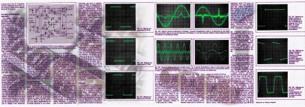
Please, can you me what is the frequency response and the slew rate of the 20W or the 30W ? And, if there are measured values, with what transistors ?
Rise time 500-600 ns (approx). FR up to 1 MHz (-3 db). And yep - excellent stability on capacitance load.
Attachments
Hey all
I was just wondering if anyone could take a moment to help me get an idea of how to upgrade my Mini Hiraga amplifier ? I think its lacking in the higher frequency, the F5 Turbo and F5 sounded better to my ears.. however...
Jean Hiraga's Le Monstre (In car amp format, 12volts) * Riki Buckingham
It is running from a 12v to 24v SMPS but Im going to switch to 240v to 24v PSU soon, is this a good idea ? perhaps I could go higher rail voltage ?
Any help really appreciated!!

Sorry I don't have a Schematic but originally the power supply and chassis is a car amplifier, Ill try and find what model it was. some Scandinavian company.
Its a Magnat RX22 and here is the PDF for Schematic
http://monitor.espec.ws/files/rx22reva1_526.pdf
Im trying to make the output voltage higher but not sure where to start, I think perhaps this may help.
https://www.electroschematics.com/11116/hack-pc-smps/
Its a Magnat RX22 and here is the PDF for Schematic
http://monitor.espec.ws/files/rx22reva1_526.pdf
Im trying to make the output voltage higher but not sure where to start, I think perhaps this may help.
https://www.electroschematics.com/11116/hack-pc-smps/
Now with 26v rails and a large heat sink attached for extra cooling, Interesting the bias takes longer to rise ? and it does not reach past 0.38v so Ill re-adjust the bias. The conversion from the original amp to this new one went well but it did take me 4 days instead of the 4 hours I thought it might!
For some reason I have one transistors on one side getting a lot hotter than the other and I cant think why. I'm touching the aluminum metal bar holding down the transistors shown in the pics any thoughts ? the bias is actually a little lower on the hotter side. Ive tried replacing the thermal grease and pads on that channel but no change. also I realized that the bar holding the transistors down has pressure in the middle so the pressure is not uniform over the transistors, perhaps this may be the issue perhaps not as its only one channel that's getting too hot.
There is however on the hotter side a small out dent on one of the transistors in other words the transistor is not perfectly flat it has a small defect on the bottom which may be stopping it stay flush and uniform on the heatsink. Perhaps this is the time to change to other transistors ? I heard some others sound better in this amp.


More pictures and write up/info on my website here
It does sound a lot better now, a lot more authoritative, dynamic, transparent etc
For some reason I have one transistors on one side getting a lot hotter than the other and I cant think why. I'm touching the aluminum metal bar holding down the transistors shown in the pics any thoughts ? the bias is actually a little lower on the hotter side. Ive tried replacing the thermal grease and pads on that channel but no change. also I realized that the bar holding the transistors down has pressure in the middle so the pressure is not uniform over the transistors, perhaps this may be the issue perhaps not as its only one channel that's getting too hot.
There is however on the hotter side a small out dent on one of the transistors in other words the transistor is not perfectly flat it has a small defect on the bottom which may be stopping it stay flush and uniform on the heatsink. Perhaps this is the time to change to other transistors ? I heard some others sound better in this amp.
An externally hosted image should be here but it was not working when we last tested it.
More pictures and write up/info on my website
hereIt does sound a lot better now, a lot more authoritative, dynamic, transparent etc
Last edited:
hi all,
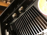
it has been few months that i've been enjoying my Hiraga. amp boards are from Jim's audio off ebay.
few days earlier, one of the amp board stopped working. not sure what is causing the issue, but the moment i connect the amp board to power supply, R14 resistor [0.33 Ohm, 5 W - the one on the right top side in the below pic] burns red hot and gets destroyed. i tried replacing resistor and Q8[MJE15034] driver transistor as well but of no use [even the old transistor reads fine on DMM]. can anybody help me in identifying the issue?
-i've measure the power input to board and it is within the limits.
-output transistor seems to be fine too [i've not removed this from the heatsink for measurement though]
Last edited:
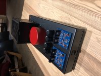
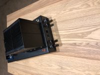
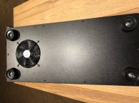
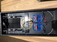
Finally finished this little fun side project. Used KSA992/KSC1845 on the front end and MJE15029/28 for drivers on one board 2SA1837/2SC4793 on the other - have no idea how that happened they were built several years ago. Outputs are MJ15022G / 23G
Still need to have faceplates made - I made 3 of the Chassis years ago too - need to get a 5V DC supply for the fan going as well before I Bias at full value - right now they are biased at 800mA.
Smooth sound with lots of detail - a remarkable design.
Good Listening
Peter
they were built several years ago. Outputs are MJ15022G / 23G Still need to have faceplates made - I made 3 of the Chassis years ago too - need to get a 5V DC supply for the fan going as well before I Bias at full value - right now they are biased at 800mA.
Smooth sound with lots of detail - a remarkable design.
Good Listening
Peter
Attachments
hi all,
it has been few months that i've been enjoying my Hiraga. amp boards are from Jim's audio off ebay.
few days earlier, one of the amp board stopped working. not sure what is causing the issue, but the moment i connect the amp board to power supply, R14 resistor [0.33 Ohm, 5 W - the one on the right top side in the below pic] burns red hot and gets destroyed. i tried replacing resistor and Q8[MJE15034] driver transistor as well but of no use [even the old transistor reads fine on DMM]. can anybody help me in identifying the issue?
-i've measure the power input to board and it is within the limits.
-output transistor seems to be fine too [i've not removed this from the heatsink for measurement though]
View attachment 701233
View attachment 701229
Hi Som, did you figured out yet? I think your output blew.. Been through that..
Finally finished this little fun side project. Used KSA992/KSC1845 on the front end and MJE15029/28 for drivers on one board 2SA1837/2SC4793 on the other - have no idea how that happened
Still need to have faceplates made - I made 3 of the Chassis years ago too - need to get a 5V DC supply for the fan going as well before I Bias at full value - right now they are biased at 800mA.
Smooth sound with lots of detail - a remarkable design.
Good Listening
Peter
Nice! You guys are making such a nice looking finished projects. I have no problem making pcb, drilling holes, soldering parts, adjusting bias, making it all working, but putting it in nice box with neat front is a pain.
Hi Som, did you figured out yet? I think your output blew.. Been through that..
Hi Sergiu! how are you?been long..
not yet, i've exhausted my supply of resistors and driver transistors. amp board is still lying outside. strangely all the components read fine on DMM. probably there must be some kinda short on the pcb while de-soldering - difficult to find out though.
output transistor measures fine on DMM - will have a look at it again. if Output has blown it would be a pain to source the pair again!
might have to think about locally available alternate options.
worst case, I'll order one set of amp board from Jim's.
- Status
- This old topic is closed. If you want to reopen this topic, contact a moderator using the "Report Post" button.
- Home
- Amplifiers
- Solid State
- Hiraga 20W class A