Hi Al,
Sounds like a good idea
-Dan
Hi Dan, I finished a F5 clone the last days, with these big transistors. Big fun!
Hows life behind the soldering iron, any time left?
albert
The only time I've seen that happen was when an output transistor fried. Is it 12V positive or negative? That should help you know which is bad.
It may not be a bad transistor, just one that is not conducting because of a bad connection or something wrong upstream.
I'm sure someone else will have other, better, ideas.
It may not be a bad transistor, just one that is not conducting because of a bad connection or something wrong upstream.
I'm sure someone else will have other, better, ideas.
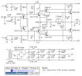
forgot to tell that output transistors i use are 2sa1302 and 2sc3281. i've replaced a fried transistor 2sa632, the output voltage is 1,7v and the 5w resistors heat up very badly. oh, and this is schematic, that i've used www.tcaas.btinternet.co.uk/hiraga3fig1.gif
Last edited:
either one or both (i did the latter)
I had selected the input pairs rigorously and tested this first without the output trying to get about 1.000 volt across the pots (0.4 for the output + 0.6 for the driver Vbe; this is fine-tuning);
- when the output is connected, then course the adjustment pot must be really centered if you go this way. Otherwise the collector pots interacts. This is similar in concept as the F5 uses.
")
Greetings,
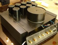
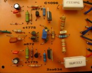
I am newbie in diy and also electronic.I have tried to build the Hiraga super class a based on the schematic that Dan has provided.First it was not working at all.I figured that I had plugged some devices the wrong way.plus when Dan has shortened some transistors I had done it for sure too. now it's working in a way but the problem is that while the output stage transistors are running quite cold the 2sa634/1096 are getting hot.voltage after the 22volt zeners are 23.38 the other voltage and currents that the original schematic suggest are quite the same.but across the 0.33 5W resistors the voltage drop is something like 7 millivolts and as I understand a very little current must be flowing there.The voltage rails are 35.I would really appreciate any help.
Here are some pictures;Ashkan
Attachments
Hello
There are several issue there just look at your set up
The heat sink is to small specially mounted that way how you use it. You lose the heat sink 40% capacity at least.
300VA transformer at that voltage enough for one chanel only. I used at the M Hiraga used 300VA at 12V power supply.The transformer was at least 45-50C warm or higher..
Please check the transistors are all the right place? also after measure all the resistors.
The Class A so simple amp to me always worked with any transistor I chose.
Please check the PNP and NPN to be the right place, also the pin out to. The driver transistors are not supposed to be that warm, check all the resistor value after goes to the power transistors.
Please send a copy from the schematic with the parts U use so I can be able to help.
35V to high that will kill any power transistor if you go with full Class A bias.
Greetings Gabor
Last edited:
Hi Gabor
Dan amplifier was my refrence. 420 X 180 X 35 mm. Mine is 600 X 200 X 40 total. But you are right, the way I have instaled them is not that effective. I could not build the enclosure from scratch.so I used a premade one and since its dimensions are 320 X 280 X 100 mm I thought more heat sink can be implemented this way. about the transformer I only have this one right now. doy think that I can run the amp with this one even in class AB? If I get the confidence I will build another one with the pcb that you suggested later. here is the schematic;
Dan amplifier was my refrence. 420 X 180 X 35 mm. Mine is 600 X 200 X 40 total. But you are right, the way I have instaled them is not that effective. I could not build the enclosure from scratch.so I used a premade one and since its dimensions are 320 X 280 X 100 mm I thought more heat sink can be implemented this way. about the transformer I only have this one right now. doy think that I can run the amp with this one even in class AB? If I get the confidence I will build another one with the pcb that you suggested later. here is the schematic;
Attachments
Here is another picture. I have replaced the 1k8 resistors for 3W. but I learned that I have to replace them again to set the bias. The R33 5W resistors are 1.1R ( this is what the multimeter shows) everything else is the same as schematic.The voltage drop across 5W resistors are very small(0.007 volt) ;
Attachments
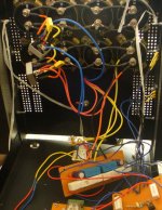
And here another one, I have made some holes in the encosure and the output transistors are mounted directly on the heatsink.Here is the power supply schematic;Solid State Power Amplifier Supply Part 3
Attachments
- Status
- This old topic is closed. If you want to reopen this topic, contact a moderator using the "Report Post" button.
- Home
- Amplifiers
- Solid State
- Hiraga 20W class A