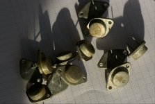
Well, I have a batch of original Toshiba 2SJ55 and 2SK175 - how would that do? Absolute thermal stability and a veritable hot - hot monstre. What do you think?
albert
Sounds good albert do you have alot of them ? I might be interested
-Dan
Hi Dan,
I have some ten pairs, so I can even successfully match them. They are refurbished, outside is rusted to a little extent. But hey, they are the most searched for components . . .
I bought them in Guangzhou when I worked there a couple of years back. Always on the lookout.

How about a 20W or 30W Hiraga Le Classe A with these components, of course the output configuration remains the same (with the 2SA634/1k8 and its base resistor of 0,47 ohm. Just add a stopper resistor. It's just not noir et vert anymore .
.
albert
I have some ten pairs, so I can even successfully match them. They are refurbished, outside is rusted to a little extent. But hey, they are the most searched for components . . .
I bought them in Guangzhou when I worked there a couple of years back. Always on the lookout.

How about a 20W or 30W Hiraga Le Classe A with these components, of course the output configuration remains the same (with the 2SA634/1k8 and its base resistor of 0,47 ohm. Just add a stopper resistor. It's just not noir et vert anymore
albert
spec sheet
Hi Dan,
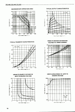
Here are the specsheets for these output transistors. (from AmpsLab site )
)
View attachment 2sj55.pdf
The J55 can be seen as a beefed up version of the J50, used by Hiraga. From 7 Amp max to 8 Amp and from 160V to 180V rating. From 100Watt to 125Watt. Indeed, the case is heavier.
View attachment 2sk175.pdf
The K175 can be seen to be a heftier K135 (higher voltage rating) used in many amplifiers. It can thus also be used as a replacement for the Nemesis one-transistor amplifier.
see the comparison thermal plot of 2SJ49/50 where you see the 75 degrees transfer plot is below that of 25 degrees:

The "most important" advantages from a construction point are:
It can imho be used in a darlingnot such as the Monstre and the 20/30Watt, and in the case of the Monstre schema the collector of the driver transistors need a load resistor that is aptly chosen, I think in the same configuration as the 20W. (In his article, Hiraga says the two output stages have the 'same' configuration).
I have made an output stage based on these with a tube driver and the sound was warm and referenced to the driverstage (I used tubes like ECC35).
The drawback is that the mid-bass seems to have a kind of extra mellowness depending on the source resistor if I am right.
Note my Le Monstre has this extremely short rise-time of about half a ns as specified and the -3db is around 500 kHz... (closed loop) I expect that a large gate capacitor of a Mosfet takes long to charge, and thus will have different behavior in the stage. While upping the driver current has it's limits too. In this aspect the 20W configuration is at an advantage, as it already can be fitted with large drivers.
What would you suggest?
Many have used Mosfets in this output stage, ZenMod being one of the promotors I saw.
albert
Hi Dan,
Here are the specsheets for these output transistors. (from AmpsLab site
View attachment 2sj55.pdf
The J55 can be seen as a beefed up version of the J50, used by Hiraga. From 7 Amp max to 8 Amp and from 160V to 180V rating. From 100Watt to 125Watt. Indeed, the case is heavier.
View attachment 2sk175.pdf
The K175 can be seen to be a heftier K135 (higher voltage rating) used in many amplifiers. It can thus also be used as a replacement for the Nemesis one-transistor amplifier.
see the comparison thermal plot of 2SJ49/50 where you see the 75 degrees transfer plot is below that of 25 degrees:

The "most important" advantages from a construction point are:
- the thermal resistance is negative, so with rising power the device shuts downs.
- the output source is on the case so the two cases need not be isolates towards each other
- the sound is superb
It can imho be used in a darlingnot such as the Monstre and the 20/30Watt, and in the case of the Monstre schema the collector of the driver transistors need a load resistor that is aptly chosen, I think in the same configuration as the 20W. (In his article, Hiraga says the two output stages have the 'same' configuration).
I have made an output stage based on these with a tube driver and the sound was warm and referenced to the driverstage (I used tubes like ECC35).
The drawback is that the mid-bass seems to have a kind of extra mellowness depending on the source resistor if I am right.
Note my Le Monstre has this extremely short rise-time of about half a ns as specified and the -3db is around 500 kHz... (closed loop) I expect that a large gate capacitor of a Mosfet takes long to charge, and thus will have different behavior in the stage. While upping the driver current has it's limits too. In this aspect the 20W configuration is at an advantage, as it already can be fitted with large drivers.
What would you suggest?
Many have used Mosfets in this output stage, ZenMod being one of the promotors I saw.
albert
Hi Al,
I think you could probably transplant the out put pair for these mosfet and change the resistors like you suggest however bias would need some attention and also a couple of other resistor values
The benefit would be if you started with just a resistive 8 ohn load for testing and say 9-12V split rail you could probably sort these issues out on the test bench before hitting the amp with a larger supply (that is what i did with the monstre and le class A recently)
I personally opted for 2SC5200/2SA1943 in Le Class A however a Vfet monstre could be something really special - if you can you should try it!
-Dan
Sounds good albert do you have alot of them ? I might be interested
-Dan
Daniel, I tried to PM you but you have PM's off
I suggest a swap: for the 2SJ55 and 2SK175 Toshiba FETS I posted about.
I plan to make a matching set-up.
Then you could get two matched pairs from me, and you
- send me a fitted PCB (for example Le Classe A - such as sold by dieroehre on ebay if that is good quality)
- with equally matched input pairs and drivers - you do the hard work there (I haven't seen a seller yet with Le Classe A PCB's fitted and stocked but Le Monstre has a good supplier on ebay)
- A collector resistor from the driver to the opposite rail of approx 6.8k would be needed as the Fets can't source a current on the gate.
- I like the BD140 /BD139 for driver because these are so very linear. You saw how that Lineup uses them in the Le Monstre
- - without the outputs of course and without the output resistors. [I plan to use 1ohm2 output resistors; Hiraga advises 1 ohm for the output pairs with fets in this Le Classe A article]
How's that for a deal (it's a steal, I know
 ).
).I do understand that with a FET output, the Le Monstre configuration would be interesting too, if run at minimum 20 V and 1,5A.
albert
(It would be nice if this were theoretically spiced before building.)
Hi Albert,
Sorry I will check my PM and see what is wrong with it.
I only just saw this message !!!!!!
Just before we go done this path I better check out the datasheets of these parts closely, but your idea sounds good so far
Did you link/post the datasheets I remember seeing them breifly.
-Dan
Sorry I will check my PM and see what is wrong with it.
I only just saw this message !!!!!!
Just before we go done this path I better check out the datasheets of these parts closely, but your idea sounds good so far
Did you link/post the datasheets I remember seeing them breifly.
-Dan
Hey, al.I like the BD140 /BD139 for driver because these are so very linear. You saw how that Lineup uses them in the Le Monstre[/I]
Actually BD139/140 seems not be the top choice.
I changed to another pair of TO-126.
2SC2911/2SA1209
And they lowered THD considerably compared to BD139/140.
It should be same for Hiraga 20 Watt
Daniel,
The types I have are higher power and higher voltage than the traditional 2SJ50/2SK135.
- of course I do think a collaborative development path would be good; why not create a new PCB (that even could be made with 'military style' fully riveted component holes). At least my bad habit is to change what is working good.
Let's source the crowd.
Since ages, discrete input transistors are used in Le Classe A. But why not use dual transistors. Like MAT01 (NPN)/, MAT02 (also NPN, Hfe 650) and Mat03 (PNP, hfe 150). This type of devices might be interesting, as they have advantages over separate, discrete transistors in the input stage:
Too bad: The MAT02 AND MAT03 CAN NOT BE MATCHED - different Hfe.
Other newer types are the LS310(NPN) and LS350(PNP) Series Monolithic Dual Transistors can be matched because of similar Hfe 150.
When re-designing a PCB, the various footprints of such devices and various discrete components could be catered for.
Good idea?
albert
The types I have are higher power and higher voltage than the traditional 2SJ50/2SK135.
- of course I do think a collaborative development path would be good; why not create a new PCB (that even could be made with 'military style' fully riveted component holes). At least my bad habit is to change what is working good.
Let's source the crowd.
Since ages, discrete input transistors are used in Le Classe A. But why not use dual transistors. Like MAT01 (NPN)/, MAT02 (also NPN, Hfe 650) and Mat03 (PNP, hfe 150). This type of devices might be interesting, as they have advantages over separate, discrete transistors in the input stage:
And this will apply to the input stage of the Le Classe A too, even though the transistors are differently configured.A fundamental requirement for accurate current mirrors and active load stages is matched transistor components. Due to the excellent VBE matching (the voltage difference between VBEs required to equalize collector current) and gain matching, the MAT03 can be used to implement a variety of standard current mirrors that can source current into a load such as an amplifier stage. mat03 datasheet
Too bad: The MAT02 AND MAT03 CAN NOT BE MATCHED - different Hfe.
Other newer types are the LS310(NPN) and LS350(PNP) Series Monolithic Dual Transistors can be matched because of similar Hfe 150.
When re-designing a PCB, the various footprints of such devices and various discrete components could be catered for.
Good idea?
albert
Hi Al,
Sounds like a good idea unfortunately I cant take you up on your offer at the moment (sadly), With a 9 month old son and I just started a new job i don't have much time for new projects I have too many happening at once !
-Dan
No problem Dan, have fun with your son and luck with your job!
albert
hello all. i need a bit of help since i think my problems have to do with inexperience. i built the hiraga 20 watt using the boards from diy world in germany. the left channel works well but the left has much less gain and major distortion. i am getting 22 volts positive and negative out of the power supply, but when i connect the speaker to the left channel the positive goes down to 19 volts. any advice on where to take it from here other than to chuck everything out and try fishing?
hello all. i need a bit of help since i think my problems have to do with inexperience. i built the hiraga 20 watt using the boards from diy world in germany. the left channel works well but the left has much less gain and major distortion. i am getting 22 volts positive and negative out of the power supply, but when i connect the speaker to the left channel the positive goes down to 19 volts. any advice on where to take it from here other than to chuck everything out and try fishing?
Did you check swinging with your oszilloscope?
Checked solder joints and correct parts on board?
Regards
Sam
Hi Earless,
a good way to find out what is wrong without being scared of smoke, is to use a 10 ohm resistor instead of the 0,33 ohm resistor. The current to the output transistors drops to some 55 mA. Devices will not get hot. But the DC working position remains the same. You don't have to attach a load (it is loaded already by 300 ohms feedback).
Then look how the DC midpoint reacts to changing the cursor position.
It looks like there is imbalance in the both sides (positive and negative).
Test to see if the voltage over the 1k5 resistors is the same positive and negative; I suspect some error will show up.
(Don't worry. I have had similar problems. Mostly having devices plugged in the wrong way... )
)
albert
a good way to find out what is wrong without being scared of smoke, is to use a 10 ohm resistor instead of the 0,33 ohm resistor. The current to the output transistors drops to some 55 mA. Devices will not get hot. But the DC working position remains the same. You don't have to attach a load (it is loaded already by 300 ohms feedback).
Then look how the DC midpoint reacts to changing the cursor position.
It looks like there is imbalance in the both sides (positive and negative).
Test to see if the voltage over the 1k5 resistors is the same positive and negative; I suspect some error will show up.
(Don't worry. I have had similar problems. Mostly having devices plugged in the wrong way...
 )
)albert
Well,
I have been itching to build something lately and I just received my transistors based upon Dan's schematic.
I have a spare 18V dual secondary 300VA xformer around. I plan to P2P a PSU using dual rectifiers and probably 4X39,000 or 4X47,000 if budget allows based on what I have done for some Pass amps I have built. Not that I want to go cheap but this combination has worked well in 3 other amps I have built.
Chassis will be a HiFi2000 type with sufficient heatsinks similar specs to what I used for my F5.
I have the board layout complete based very much upon the original schematic. I plan to etch my own boards maybe this weekend.
I look forward to putting this into the listening rotation!
Hello
Did someone ever used these schematic .
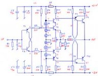
It is very interesting with those LEDs and the extra par transistor ..
I use the orig.schematic can these be better than that ?
Any comment on these please .
Probably I will try these interesting schematic with those mods.
Greets
Hi Gaborbela,
How has things followed up with this implementation, I saw you had a PCB made of Tadiams' posting.

I am interested in this version with cascode.
How did it materialise?
albert
- Status
- This old topic is closed. If you want to reopen this topic, contact a moderator using the "Report Post" button.
- Home
- Amplifiers
- Solid State
- Hiraga 20W class A