The parallel resistor is no big deal.The resistance at that point is 470 ohm 5 watt which could be a combo of two 3watters. The rail caps are a simple refinement which may make little or no difference in performance.
I agree that these are no big deal (this is what I meant by "trivial"...). By "that point" you mean R11/R12 and R13/R14, right? If so, then this is half the resistance in the original, suggesting that you could easily use these boards with the original voltages by putting just one of the resistors, and still put the second one in and try increasing the rails later... (or the other way around, I guess...)
I'm not sure why I 'm doing this project but if for no other reason I can make a comparison with my ZEN(s).
As chance would have it, I am doing a mini-aleph-j with BF862 to do the reverse comparison, among other things.... (check out
http://www.diyaudio.com/forums/pass-labs/152379-mini-aleph-using-bf862-possible.html
to see all the good advice I received, if you're interested.)
There is no bias or other info included with this package . I'm eyeing a cap multiplier for power but also considering CLC.Can do about 68,000uf without spending a dime. There is no reason why I'd have to adhere to 22v rails and may decide not to .Have a 24vct 10 amp trans sitting idle.
Again thanks for the help")
Original bias is around 0.5 A, if memory serves (Dan?) but with the higher rails and lower resistance values maybe the kit is designed for higher? I use a cap multiplier with all of mine, which has worked well, although YMMV.
As a final thought, I agree with Dan that maybe this should be moved to the other thread - since it plainly is about the Monstre and not the Hiraga 20W in this thread's title...
Cheers
Nigel
The resistors in the PSU are part of the line noise filter. The work as a sort of low pass for line noise. You will notice that there is one large cap (per rail) ahead of the resistor and 2 after. As the resistor will limit current a bit, the big caps downstream help to supply peak current.
As far as I remember, the amp design does not have a very good PSRR, so a lot of effort and care need to be taken to keep noise low. Thus the copper bars in the PSU and very symmetric wiring.
Running at 18.5V is going to take some important recalculation of bias. It's easy to go too far and burn up the amp. I know!
Do anyone who build this amp can tell me something about resistors in PSU (CRC filter) and how this resistor improves the sound. Also I'm interesting for PSU voltage. I'am using about 18.5 VDC and constantcurent draw of 1.3A.
Which amp are you building? Le Classe A 20W, or Le Monstre 8W?
...Running at 18.5V is going to take some important recalculation of bias. It's easy to go too far and burn up the amp. I know!
If Glogov_Kolac is building the 20W Classe A then 18.5V is pretty normal... the original article gives +/- 19 to 21 volts... Bias is given as 0.8 to 1A. I wonder if this thread is starting to get confused between these two amplifier designs.
Cheers
Nigel
I wonder if this thread is starting to get confused between these two amplifier designs.
Yes! Well at least I was.

You are correct, sir.
I agree that these are no big deal (this is what I meant by "trivial"...). By "that point" you mean R11/R12 and R13/R14, right? If so, then this is half the resistance in the original, suggesting that you could easily use these boards with the original voltages by putting just one of the resistors, and still put the second one in and try increasing the rails later... (or the other way around, I guess...)
As chance would have it, I am doing a mini-aleph-j with BF862 to do the reverse comparison, among other things.... (check out
http://www.diyaudio.com/forums/pass-labs/152379-mini-aleph-using-bf862-possible.html
to see all the good advice I received, if you're interested.)
Original bias is around 0.5 A, if memory serves (Dan?) but with the higher rails and lower resistance values maybe the kit is designed for higher? I use a cap multiplier with all of mine, which has worked well, although YMMV.
As a final thought, I agree with Dan that maybe this should be moved to the other thread - since it plainly is about the Monstre and not the Hiraga 20W in this thread's title...
Cheers
Nigel
Oddly I'm doing a Hiraga thing ,have mini-aleph and am somewhat involved with BF862 and have been in touch with the same Serbian High Tech Mafia .
Would be interested in your take with your Hiraga.
Oddly I'm doing a Hiraga thing ,have mini-aleph and am somewhat involved with BF862 and have been in touch with the same Serbian High Tech Mafia .
Would be interested in your take with your Hiraga.
Hi Sandy,
To avoid polluting this thread with stuff which is off-topic perhaps we could put discussion of the mini-aleph-j stuff in the thread I mentioned above. (It sounds terrific...)
By my "take" do you mean my (subjective) comparison of sound of the two? Delighted to talk about any of this stuff, but I should point out that my Hiraga 20W has been retired in favor of the Pass F5 in the living room (main rig) for a while now, so I can only compare with the Le Monstres, which are farther from the original design. This might also be better in the other thread, since it doesn't really have anything to do with the amp in the title of this one.
Cheers
Nigel
Hi, guys! What do you think about the scheme, it is good?
What do you think about the electronic components enclosed in red on the scheme in my post?
I think these electrics elements limit the ability of the amplifier. What do you think about this?
Do you think that, they are only for the limited bandwidth and they are necessary?
What happens if we remove it?
Attachments

Question
Hi, guys!
What do you think about the scheme, it is good?
What do you think about the electronic components enclosed in red on the scheme in my post?
I think these electrics elements limit the ability of the amplifier.
Do you think that, they are only for the limited bandwidth and they are necessary?
What happens if we remove it?
Attachments
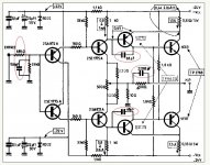
The scheme is identical with others scheme in old posts, but my question is for the condensers 68pF and 2200pF, which skipped the transistors and which is in a feedback enclosed in red on the scheme in my post. I think these elements limit the ability of the amplifier and make it worse.
What happens if we remove it?
What do you think about the poor damping factor of scheme?
What happens if we remove it?
What do you think about the poor damping factor of scheme?
Hi,
The schematic above appears to be for the 30W version of this amp. I've attached below the schematic for the 20W version, which I took from the "class a amplifier site", which has the original L'Audiophile articles (in English translation as well as the original French.) Note the rail voltages compared to yours above, the bias current, and that there are (almost) no capacitors... I'll leave people who understand these things better than I do to explain why 30W needs them and 20W doesn't, but at least the schematic shows that they aren't essential in principle.
Cheers
Nigel
Attachments
Hi Guys...
AndrewT - Lol your prize is frustration fpr spotting a double post ??!???!
Nelsonvandal/whitesnake
These capacitors locations are pretty standard fare on a lot of amps.
The capacitor closest to the input is a HF filter to limit the amplifiers frequency response, the 68pF caps (yes silver mica is good here) are also for HF stability - i have tried with and without the the results are similar but the amp is more prone to very small level HF oscillations on leading edge of the signal. My understanding is these caps provide some degree of local feedback and help the slightly different - yet relatively low values of Cob for the 2SA634/2SC1096 pair.
The capacitor on the feedback resistor is also pretty normal - once again used for HF stability / HF roll off characteristics.
My personal opinion is the point in this circuit which the capacitors are placed do not affect the sound adversly - they are all there to correct any potential HF issues and improve with difficult reactive loads in an other wise very stable yet fast amplfier.
Hope this helps
-Dan
masag1,
No.Leaving those capacitors could bring a lot of swing into your amp.
Depends of your layout and wireing.
Compensation is needed to get a nice square wave.
- Status
- This old topic is closed. If you want to reopen this topic, contact a moderator using the "Report Post" button.
- Home
- Amplifiers
- Solid State
- Hiraga 20W class A