what do the noises+hum measure?
Do these measurements change when you test various input connections?
The lowest measurement should come with the inputs shorts. Next lowest should be with the two interconnects attached but with their remote ends shorted.
If you connect the barrels of the remote shorted ends you may get a much larger H+N measurements. All of these tests should give a non audible signal at the speaker/s for a well wired amplifier, only measurements can tell them apart when the amp is wired properly.
Your RF attenuation filter at the input is set to ~1.6MHz.
Don't you think that is a bit/lot too high?
Your DC blocking filter at the input is set to 0Hz.
Don't you think that is set a bit/lot too low?
Last edited:
what do the noises+hum measure?
Do these measurements change when you test various input connections?
The lowest measurement should come with the inputs shorts. Next lowest should be with the two interconnects attached but with their remote ends shorted.
If you connect the barrels of the remote shorted ends you may get a much larger H+N measurements. All of these tests should give a non audible signal at the speaker/s for a well wired amplifier, only measurements can tell them apart when the amp is wired properly.
with shorted inputs, DC Offset measures around +/- 0.10 millivolt
i would test with with other combinations and report back.
Your RF attenuation filter at the input is set to ~1.6MHz.
Don't you think that is a bit/lot too high?
Your DC blocking filter at the input is set to 0Hz.
Don't you think that is set a bit/lot too low?
sorry, if you're referring to circuit then i'm not sure how to calculate above parameters from it
 .
.DC offset is neither noise nor hum. You need an AC voltage measurement using a 199.9mVac or 199.99mVac reading voltmeter.with shorted inputs, DC Offset measures around +/- 0.10 millivolt
F-3dB = 1/{2 Pi R C}i would test with with other combinations and report back.
sorry, if you're referring to circuit then i'm not sure how to calculate above parameters from it
If you want to pass 20kHz, then why are you setting the RF attenuation filter to 1.6MHz?
DC offset is neither noise nor hum. You need an AC voltage measurement using a 199.9mVac or 199.99mVac reading voltmeter.F-3dB = 1/{2 Pi R C}
If you want to pass 20kHz, then why are you setting the RF attenuation filter to 1.6MHz?
thanks Andrew!
ok, i'll check the ACV across the output once i get home [hopefully my multimeter is capable of small mVac measurements]
even I was calculating the values based on formula found online. R of 680ohms C of 150pF is from the original circuit of Hiraga which Jim's audio also has replicated and so does Dan's amp. not sure of changing those values.
Last edited:
Hi Som,
First you should localise the source of your noise, disconect the input cable and if the buzz dissapears then you have an input cable issue (its too long and its picking up noise). If the buzz remains after removing the cables then you have a grounding issue. Read the Hiraga articles about wiring or other online articles about star ground.
The input filter is ok. My amp runs dead quiet with that filter.
It is sufficient to have 1.65A bias when mains are lower. I adjusted the amp in daytime when the mains are lower. It doesnt matter if bias goes up, everything is ok if you have sufficient cooling....this is why i recomended huge rads and oversized trafos when going HIGHER THAN 1.5A bias. I discovered that the temp goes up in the roof when overbiasing.

You will see that the amp stabilises after about 45mins. About the bias procedure: i adjust it first in two minutes, then again in 30mins then after another 30 minutes, so this should take you about 1hour, and after each bias adjust, please readjust the offset.
Still i advice you to buy a cheap DMM with temp measurement, measure the temps, then add the DMM temp tolerance to find the actual temp of your rads outputs. The rads temp should not pass 65 degrees celsius per radiator if you want about 15 years of high quality auditions... Another aspect (very important) is that you should lift the rads at least 5 cm from the ground ( at tests and at the finall amp encloshure) so that the stack effect between the rad fins will 100% kick in and keep the temps steady.
And as our colleague Andrew pointed out very well here use the thinnest mica you can get.
Hope it goes well.
Cheers
Sergiu
First you should localise the source of your noise, disconect the input cable and if the buzz dissapears then you have an input cable issue (its too long and its picking up noise). If the buzz remains after removing the cables then you have a grounding issue. Read the Hiraga articles about wiring or other online articles about star ground.
The input filter is ok. My amp runs dead quiet with that filter.
It is sufficient to have 1.65A bias when mains are lower. I adjusted the amp in daytime when the mains are lower. It doesnt matter if bias goes up, everything is ok if you have sufficient cooling....this is why i recomended huge rads and oversized trafos when going HIGHER THAN 1.5A bias. I discovered that the temp goes up in the roof when overbiasing.
You will see that the amp stabilises after about 45mins. About the bias procedure: i adjust it first in two minutes, then again in 30mins then after another 30 minutes, so this should take you about 1hour, and after each bias adjust, please readjust the offset.
Still i advice you to buy a cheap DMM with temp measurement, measure the temps, then add the DMM temp tolerance to find the actual temp of your rads outputs. The rads temp should not pass 65 degrees celsius per radiator if you want about 15 years of high quality auditions... Another aspect (very important) is that you should lift the rads at least 5 cm from the ground ( at tests and at the finall amp encloshure) so that the stack effect between the rad fins will 100% kick in and keep the temps steady.
And as our colleague Andrew pointed out very well here use the thinnest mica you can get.
Hope it goes well.
Cheers
Sergiu
thanks Sergiu!
i have static resistors for bias resistors: it is at 35.7K Ohms which results in a Q current of 1.58Amps in the day time voltage.
i'll follow your procedure to isolate the noise and reduce temperature!
right now i'm using thin Kapton tape to isolate transistor from copper heat spreader with thin layer of thermal goop applied on either side.
Last edited:
I have planned to use Capacitance Multiplier as a Power Supply for this 30 watt Amplifier. I have made a CM as per this link Capacitance Multiplier Power Supply Filter.
I have made the PCB as per below layout, (Diode will be mounted separately)
For the thin tracks I had already coated with a thick layer of Soldering.
I have made some changes which are as below.
1. Capacitor I have used is 15,000 uf instead of 10,000uf.
2. Instead of TIP i have used 2SC5200 & 2SA1943
Can someone please specify what are the disadvantages of using a Capacitance Multiplier. How will it perform with respect to the big heavy capacitor Banks used in Original built.
Regards,
Sadik Bhatkar
I have made the PCB as per below layout, (Diode will be mounted separately)
An externally hosted image should be here but it was not working when we last tested it.
For the thin tracks I had already coated with a thick layer of Soldering.
I have made some changes which are as below.
1. Capacitor I have used is 15,000 uf instead of 10,000uf.
2. Instead of TIP i have used 2SC5200 & 2SA1943
Can someone please specify what are the disadvantages of using a Capacitance Multiplier. How will it perform with respect to the big heavy capacitor Banks used in Original built.
Regards,
Sadik Bhatkar
Thanks AndrewT... I was hoping for an answer form you.. Thanks for the quick reply. So this means the Cap Multiplier is not recommended for this Amp. Is there any chance, by doing some modifications I can use this and will perform well. If heat is issue then i have a good size of heat sink to deal with it.
Sadik
Sadik
Better to use Al2O3 or AlN, than mica.Hi Som,
First you should localise the source of your noise, disconect the input cable and if the buzz dissapears then you have an input cable issue (its too long and its picking up noise). If the buzz remains after removing the cables then you have a grounding issue. Read the Hiraga articles about wiring or other online articles about star ground.
The input filter is ok. My amp runs dead quiet with that filter.
It is sufficient to have 1.65A bias when mains are lower. I adjusted the amp in daytime when the mains are lower. It doesnt matter if bias goes up, everything is ok if you have sufficient cooling....this is why i recomended huge rads and oversized trafos when going HIGHER THAN 1.5A bias. I discovered that the temp goes up in the roof when overbiasing.
You will see that the amp stabilises after about 45mins. About the bias procedure: i adjust it first in two minutes, then again in 30mins then after another 30 minutes, so this should take you about 1hour, and after each bias adjust, please readjust the offset.
Still i advice you to buy a cheap DMM with temp measurement, measure the temps, then add the DMM temp tolerance to find the actual temp of your rads outputs. The rads temp should not pass 65 degrees celsius per radiator if you want about 15 years of high quality auditions... Another aspect (very important) is that you should lift the rads at least 5 cm from the ground ( at tests and at the finall amp encloshure) so that the stack effect between the rad fins will 100% kick in and keep the temps steady.
And as our colleague Andrew pointed out very well here use the thinnest mica you can get.
Hope it goes well.
Cheers
Sergiu
Are you taking into account the thickness required for the al ox spacers?Better to use Al2O3............than mica
Can you post the pcb in black & white for home etching?I have planned to use Capacitance Multiplier as a Power Supply for this 30 watt Amplifier. I have made a CM as per this link Capacitance Multiplier Power Supply Filter.
I have made the PCB as per below layout, (Diode will be mounted separately)
An externally hosted image should be here but it was not working when we last tested it.
For the thin tracks I had already coated with a thick layer of Soldering.
I have made some changes which are as below.
1. Capacitor I have used is 15,000 uf instead of 10,000uf.
2. Instead of TIP i have used 2SC5200 & 2SA1943
Can someone please specify what are the disadvantages of using a Capacitance Multiplier. How will it perform with respect to the big heavy capacitor Banks used in Original built.
Regards,
Sadik Bhatkar
Are you taking into account the thickness required for the al ox spacers?
Material of ceramic thermal spacers. Aluminum nitride better than aluminium oxide. Thickness 0.25-1 mm.., usually.
Material of ceramic thermal spacers. Aluminum nitride better than aluminium oxide. Thickness 0.25-1 mm.., usually.
Hello neighbour, do you have any domestic production of Al2O3 or AlN insulators?
edit: there is one little thing I am worried about regrding AlN, from Wikipedia
https://en.wikipedia.org/wiki/Aluminium_nitrideEpitaxially grown thin film crystalline aluminium nitride is used for surface acoustic wave sensors (SAWs) deposited on silicon wafers because of AlN's piezoelectric properties. One application is an RF filter which is widely used in mobile phones,[6] which is called a thin film bulk acoustic resonator (FBAR). This is a MEMS device that uses aluminium nitride sandwiched between two metal layers.[7]
Aluminium nitride is also used to build piezoelectric micromachined ultrasound transducers, which emit and receive ultrasound and which can be used for in-air rangefinding over distances of up to a meter.[8][9]
maybe the heat sinks and whole chassis starts to sing with the music, also I couldn't find what is the resistivity of this material, is it really good for audio application...
Last edited:
Hello neighbour, do you have any domestic production of Al2O3 or AlN insulators?
edit: there is one little thing I am worried about regrding AlN, from Wikipedia
https://en.wikipedia.org/wiki/Aluminium_nitride
maybe the heat sinks and whole chassis starts to sing with the music, also I couldn't find what is the resistivity of this material, is it really good for audio application...
Data from datasheet.
thickness 0,25 mm.
Thermal conductivity (W/m*K): AlN - 180, Al2O3 - 25.
Calculated thermal resistance (K/W): AlN - 0,004; Al2O3 - 0,03.
hi friends!
finally i got my both Hiraga mono blocks singing..
for starters there is absolutely no hiss or noise!
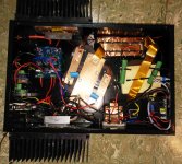
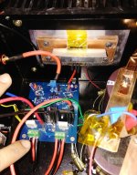
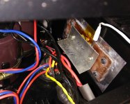
excuse the messy wiring, this is the best i could do. working with those thick wires is a PITA.

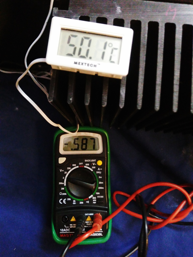
but i do have one concern: on one of the channels, bias voltage hovers around 0.6 Volts resulting in bias current of around 2Amps!! but the amp seem to normal -no overheating, music sounds the same between the 2 monoblocks. bias voltage seems to be settling at around 0.595 volts DC across the resistors. hope it won't turn out to be an issue. rail voltages are 29VDC . with or without load not much of a difference [30VDC without load]. probably due to 400VA transformer!?
been running the amps for around 1 hour in this configuration.
max temperature recorded is around 52 degree Celsius. ambient temperature is around 25 degree Celsius. i can comfortably place my fingers on the heat sink for as long as i like - it doesn't burn. also, my soft-start module has a temperature sensor which will cut the power if the temperature reaches 75 degree Celsius.

i've mounted transistors on Copper spreader which is bolted onto Aluminium heat sink. each monoblock weighs around 18kgs. i'll put up a detailed write up after some time.
will probably finish the build tomorrow if the temperature and bias stays stable for another hours or so.
finally i got my both Hiraga mono blocks singing..
for starters there is absolutely no hiss or noise!
excuse the messy wiring, this is the best i could do. working with those thick wires is a PITA.
but i do have one concern: on one of the channels, bias voltage hovers around 0.6 Volts resulting in bias current of around 2Amps!! but the amp seem to normal -no overheating, music sounds the same between the 2 monoblocks. bias voltage seems to be settling at around 0.595 volts DC across the resistors. hope it won't turn out to be an issue. rail voltages are 29VDC . with or without load not much of a difference [30VDC without load]. probably due to 400VA transformer!?
been running the amps for around 1 hour in this configuration.
max temperature recorded is around 52 degree Celsius. ambient temperature is around 25 degree Celsius. i can comfortably place my fingers on the heat sink for as long as i like - it doesn't burn. also, my soft-start module has a temperature sensor which will cut the power if the temperature reaches 75 degree Celsius.
i've mounted transistors on Copper spreader which is bolted onto Aluminium heat sink. each monoblock weighs around 18kgs. i'll put up a detailed write up after some time.
will probably finish the build tomorrow if the temperature and bias stays stable for another hours or so.
Attachments

finally i got my both Hiraga mono blocks singing..
for starters there is absolutely no hiss or noise!
excuse the messy wiring, this is the best i could do. working with those thick wires is a PITA.
Hello my friend, congrats!!
but i do have one concern: on one of the channels, bias voltage hovers around 0.6 Volts resulting in bias current of around 2Amps!! but the amp seem to normal -no overheating, music sounds the same between the 2 monoblocks. bias voltage seems to be settling at around 0.595 volts DC across the resistors. hope it won't turn out to be an issue. rail voltages are 29VDC . with or without load not much of a difference [30VDC without load]. probably due to 400VA transformer!?
The thing with the bias is that you can barelly hear this difference, but if you measure with a DMM on the output you will see that this channel has more power. With very sensitive speakers you will definetly hear this. So better adjust.
The transformer is doing just fine. The voltage drop of just 1 V is ok, dont worry about it. This is the case on each built (about 1V drop). I would sugest you measure the trafo temp also on the 2A bias and on the other channel and compare to see wich temp is more lower and convenient.
been running the amps for around 1 hour in this configuration.
max temperature recorded is around 52 degree Celsius. ambient temperature is around 25 degree Celsius. i can comfortably place my fingers on the heat sink for as long as i like - it doesn't burn. also, my soft-start module has a temperature sensor which will cut the power if the temperature reaches 75 degree Celsius.
This is very good!! But i would recomend you should measure directly on those L shape Al pads on the outputs and see how hot the outputs are. The lower the temp the better for long time exploatation. Usually its best they dont reach 65 degrees celsius or above.
i've mounted transistors on Copper spreader which is bolted onto Aluminium heat sink. each monoblock weighs around 18kgs. i'll put up a detailed write up after some time.
This is very good, especially when its time for house cleaning... My whole amp has 34kg and rests on a stand with wheels. Now i wish i had made it smaller and separating the channels entirely.
will probably finish the build tomorrow if the temperature and bias stays stable for another hours or so.
Enjoy!
Only one thing i would strongly recomend in your case, because it seems that you are using toroidal trafos: shield them.
Cheers
Sergiu
for starters there is absolutely no hiss or noise!
excuse the messy wiring, this is the best i could do. working with those thick wires is a PITA.
Hello my friend, congrats!!
but i do have one concern: on one of the channels, bias voltage hovers around 0.6 Volts resulting in bias current of around 2Amps!! but the amp seem to normal -no overheating, music sounds the same between the 2 monoblocks. bias voltage seems to be settling at around 0.595 volts DC across the resistors. hope it won't turn out to be an issue. rail voltages are 29VDC . with or without load not much of a difference [30VDC without load]. probably due to 400VA transformer!?
The thing with the bias is that you can barelly hear this difference, but if you measure with a DMM on the output you will see that this channel has more power. With very sensitive speakers you will definetly hear this. So better adjust.
The transformer is doing just fine. The voltage drop of just 1 V is ok, dont worry about it. This is the case on each built (about 1V drop). I would sugest you measure the trafo temp also on the 2A bias and on the other channel and compare to see wich temp is more lower and convenient.
been running the amps for around 1 hour in this configuration.
max temperature recorded is around 52 degree Celsius. ambient temperature is around 25 degree Celsius. i can comfortably place my fingers on the heat sink for as long as i like - it doesn't burn. also, my soft-start module has a temperature sensor which will cut the power if the temperature reaches 75 degree Celsius.
This is very good!! But i would recomend you should measure directly on those L shape Al pads on the outputs and see how hot the outputs are. The lower the temp the better for long time exploatation. Usually its best they dont reach 65 degrees celsius or above.
i've mounted transistors on Copper spreader which is bolted onto Aluminium heat sink. each monoblock weighs around 18kgs. i'll put up a detailed write up after some time.
This is very good, especially when its time for house cleaning..
. My whole amp has 34kg and rests on a stand with wheels. Now i wish i had made it smaller and separating the channels entirely.will probably finish the build tomorrow if the temperature and bias stays stable for another hours or so.
Enjoy!
Only one thing i would strongly recomend in your case, because it seems that you are using toroidal trafos: shield them.
Cheers
Sergiu
Last edited:
29V rails, 2 Amp bias, 52 degrees, 25 ambient, with those heatsinks? Are we sure?
The size of those heat sinks are 215mm Length x 153 mm Height (6 Inch) & Fins Height is 75mm. Model No N56 from the link Aluminium heatsink, Heat sink in bangalore, Heatsink stockist, Heatsink dealer, Heatsink supplier, Aluminium LED Heatsinks, Aluminium Reflector Sheets, Aluminium Caul board Sheet 2.5mm, Aluminium Plywood sheets, Aluminium Alloy Rods,plates in 2014, 7 Its a pretty big size, secondly on each heat sink only one transistor is mounted.
hi Sergiu! thanks for the detailed response!

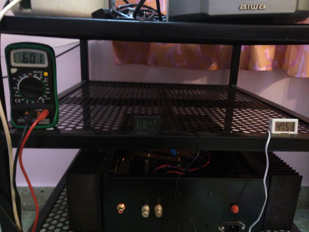
the temperature recorded is near the transistor [between al plate and copper]. those aluminium pads are quite hot to touch. i think the temperature sensor may not be efficient since the probe is cylindrical in shape [they have firm contact between the surfaces though]. but even after 3+ hours of operation i didn't see them raise above 52 degree Celsius in the afternoon.
i think bias current i quoted is wrong [even for approximation!]. max bias voltage noted is around 0.620 in the past 2 hours hours of operation resulting in the current of 1.87Amps [0.620/0.33]. rail voltages now are 30.3 VDC [it is almost 1 A.M. here now]
trafos seem to be running cool, i didn't find them hot to touch [tested now after running for about 2+ hour]. resistors in CRC are warm to touch [0.25Ohms, 30W rated].
yes, i'm using toroidals, what kind of shielding do you recommend ? steel bowl? for now it is bolted directly on chassis [epoxy potted center] and a small wooden plank on top to support CRC resistors.
@alibear, probably those numbers are slightly off as explained above. why do you think these are not realistic? is there anything that you suggest that i need to look into. heat sinks are each around 2.7kgs [one for each transistor ~ 5.5 kg for each channel]. i can feel a very good chimney effect when i hover over those heat sinks. initially while bench testing i had placed them horizontally, and those heat sinks used to get really hot - i couldn't place my fingers on them for more than couple of seconds!
thanks Sadik! for some reason, i didn't see your post until now.
Attachments

Last edited:
- Status
- This old topic is closed. If you want to reopen this topic, contact a moderator using the "Report Post" button.
- Home
- Amplifiers
- Solid State
- Hiraga 20W class A