Hi, i am curently studying, so the funds for new HI-Fi parts are low. I have a Denon PMA-925R stereo amplifier that i am considering giving an upgrade, instead of buing a new amplifier.
So i would like to have your advice on how to, and if it is a good idea?
I am considering changing the two 12000uf Elna caps to 18000uf Elna caps- are there other parts that i can change to give better sound?
The thing is that my brother has recently bought a NAD 80w amplifier, and i am amazad on the difference in sound. The NAD sounds much clearer, dynamic and powerfull, and when played loud, it has much better control of my 12" bas speakers.
Is there a way to make the Denon more dynamic and powerfull in the bas and on dynamic disharges? Or should i just forget it, and live with the thiner sound of the Denon until i have the funds for a better amplifier?
I am well aware that i will newer reach the quality of a new modern amplifier, but is it possible to make the denon better with limited funds?
Regards
Jens
Here´s a link to the manual and wirring diagrams:
Denon PMA-925R | Owners Manual, Service Manual, Schematics, Free Download | HiFi Engine
Denon PMA-925R | Owners Manual, Service Manual, Schematics, Free Download | HiFi Engine
Moin (as we say here) Jens, as it looks from the inside, it seems worth a try ...
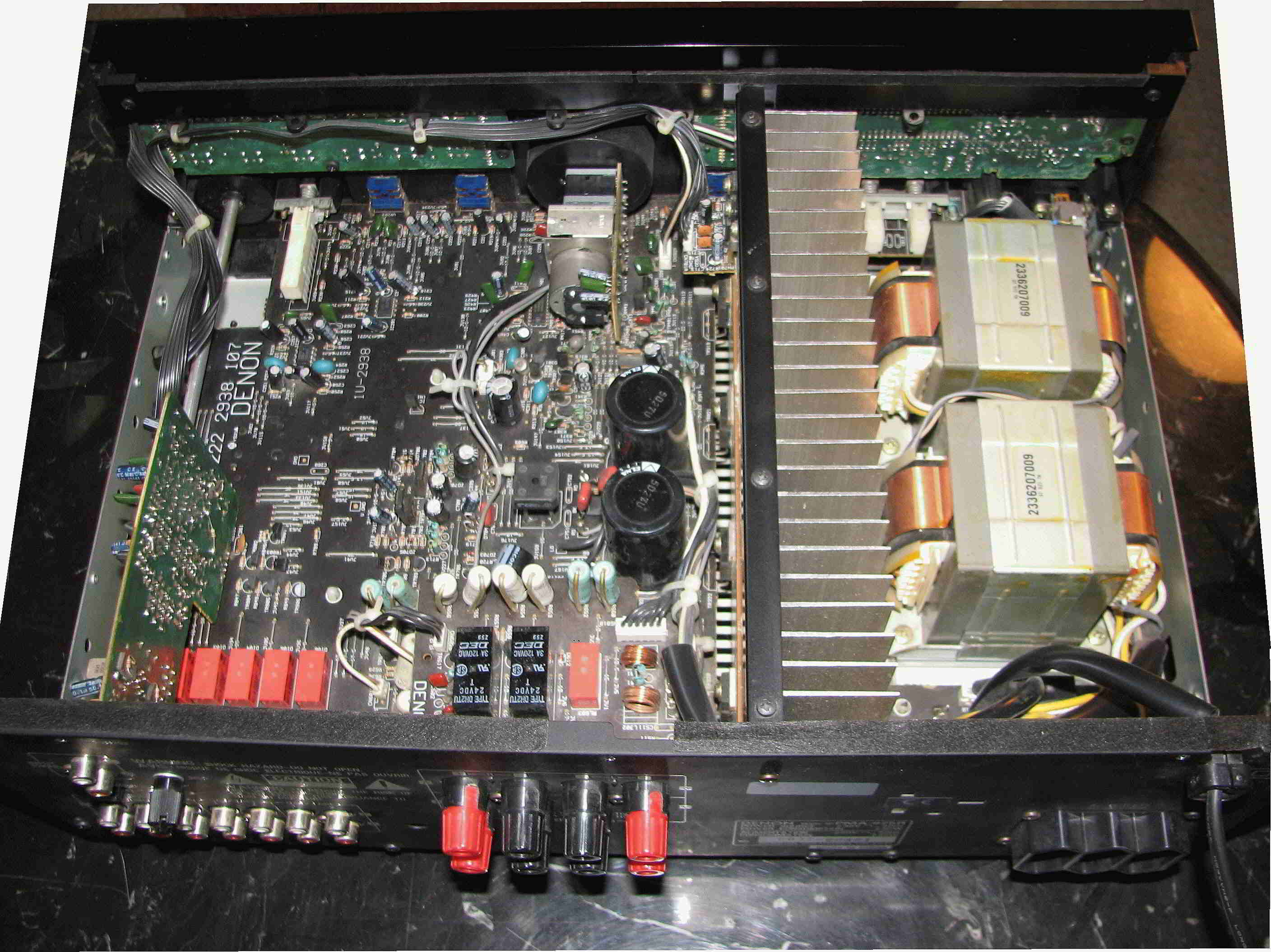
At least the transformers look decent, and there could be worse than realy switched inputs, a Panasonic plastic film potentiometer and an active bias control. Adding just some more 6000µF won't change much IMHO, you should at least double or better triple the capacitance to have an effect. There is enough space to do that, consider mounting the capacitors on veroboard and wire that arrangement to the original solder points. Use thick wire, keep it as short as possible- high currents flow there.
Change the rectifier bridge for some ultra-fast MUR860 diodes. Change the crappy BA4558 and NJM2068DDC opamps for OPA2134 (except the phono stage if you don't have a turntable) and decouple them as close as possible with 10µF Panasonic FM (or something else in that league) and 10nF film foil in parallel.
I've stored there service manual here. (Scroll down and click the 'Slow Download' icon)
Have some reading about amplifier sound and power supplies: : Amplifier Sound - What Are The Influences?, Solid State Power Amplifier Supply Part 1
Last edited:
Moin (We use that phrase here in DK to )
Thanks a lot, that was the kind of answer i was looking for. I am no electronics master, so my knowledge on how to fabricate new boards are wery limited. I asume that the new capacitors should be wired in paralell?
Can i drop the new rectifier bridges and opamps/capasitors on to the exesting board? Or do i have to fabrikate a new board to be soldered in where the stock diodes and opamps are soldered to the board?
Sorry if my questions are a bit newbee..
Regards
Desolder the bridge rectifier D702 and place the MUR860 diodes as shown in the rectifier's footprint. Quite self-explaining ...
The capacitors must be wired in parallel. You don't have to make boards. Just get a veroboard and a drill to widen the holes. Do it like that:
Use thick wire!
Change opamps IC201 and IC202 for OPA2134PA, you also could try LME49720NA. Change C213/C214 and C258/C259 for 10µF Panasonic FM or Elna Silmic or whatever with low ESR. Desolder the opamps the the capacitors, then scrape off the solder mask coating where I placed the blue dots:
There you solder the small film capactitors, no need to drill holes. Solder in the new opamps, then the small film capacitors, then the Pana FM or whatever you like.
About decoupling there is an interesting thread here. A good source for audio partss in small quantities is here.
The capacitors must be wired in parallel. You don't have to make boards. Just get a veroboard and a drill to widen the holes. Do it like that:

Use thick wire!
Change opamps IC201 and IC202 for OPA2134PA, you also could try LME49720NA. Change C213/C214 and C258/C259 for 10µF Panasonic FM or Elna Silmic or whatever with low ESR. Desolder the opamps the the capacitors, then scrape off the solder mask coating where I placed the blue dots:
There you solder the small film capactitors, no need to drill holes. Solder in the new opamps, then the small film capacitors, then the Pana FM or whatever you like.
About decoupling there is an interesting thread here. A good source for audio partss in small quantities is here.
Now i understand, thanks
It shouldnt be to difficult for me to do.
I have a question on what electrolytes to use. From the thread you have linked to, i can see that capasitors from different makes have an efect on the sound. Is there a brand that you can recomend me me to buy for the big electrolytes? I would like a bit warmer sound than the Denon have now- if it is possible?
Fancy psu capacitors
Decent psu capacitors
For the sound I can't do even only a guess. Higher capacitance gives more punch, especially on higher volumes. Have a look into the schematic and follow the signal trace from input to the speaker posts. All what is in that trace affects the sound.
Making a psu beefier is a good starting point. Do it, listen to it, then think further.
I have ordered two Mundorf M-Lytic AG 22000uF Electrolytes, 4 Elna Silmic II 10uF and 4 Obligato 0,1uF for the upamps.
The rectifiers will be Motorola MUR860, and the upamps wil be Burr-Brown OPA2134PA.
If the 22000uF dont do the job, i will order two more M-Lytic electrolytes for a total of 2x44000uF.
I cant wait to hear the result") I will of course give some feedback, when the amplifier is up and running.
I will of course give some feedback, when the amplifier is up and running.
The rectifiers will be Motorola MUR860, and the upamps wil be Burr-Brown OPA2134PA.
If the 22000uF dont do the job, i will order two more M-Lytic electrolytes for a total of 2x44000uF.
I cant wait to hear the result
I will of course give some feedback, when the amplifier is up and running.Indeed, my first attempt ever in DIY electronics was to increase the psu capacitance in a Harman Kardon PM665Vxi amplifier. That was 23 years ago (Time goes faster every day ...) Without the generous help of the nice folks here I would not know much about DIY audio, and so I'm doing my best to cnotribute. That's where I'm now, no way to achieve that without DIYaudio.com ...
More than 22.000µF isn't worth the effort IMHO. Maybe I'll have a deeper look into the Denon's schematic and give you some further advice. Pop in the bigger caps and tell me your findings, sending me a private message.
More than 22.000µF isn't worth the effort IMHO. Maybe I'll have a deeper look into the Denon's schematic and give you some further advice. Pop in the bigger caps and tell me your findings, sending me a private message.
Last edited:
You are right, the forums are a great tool to learn from other peoples eksperiences and knowledge- as long as people are willing to share them. That isnt always the case.
I will give you some feedback in a PM, and of course post it in this thread, when i have finnished the upgrade, and the amplifier is burned in.
I plan to do a comparison test with the Denon and my brothers NAD C355BBE- if it beats the NAD at the points that are my criteria for good HiFi listening, i will be amazed. But only time will tell.
Regards
And by the way- it is a very nice setup you have your self.
My next step will be a fully digital setup with connexelectronic and mini digi, with no DA converting done before just before the power amps- but that is when i am finnished with my new education.
Currently i am running the Denon 925R, a Denon CD player (it has just died), a Sony CD/DVD player and a set of DIY speakers with Peerles drivers (12" bas, 3" mid dome and a 1½" tweeter)
I am waiting for my new DAC Magic to arrive. My plan is to use the Sony DVD as a multi player with the DAC Magic, instead of the Denon CD player. I plan to run my PS3 and the TV through the dac too. I hope it will be a decent setup with the modified Denon.
Last edited:
I have changed the electrolytes, capasitors and the upamps, but i am a bit confused about how to make the new rectifier bridge. I have bought 2 MUR860G diodes, but now i think that i need 4.
Image - TinyPic - Free Image Hosting, Photo Sharing & Video Hosting
Is that right, or can i just connect pin 3 to ac and 1 to +, and the other with pin 3 to ac an 1 to -?
An externally hosted image should be here but it was not working when we last tested it.
Image - TinyPic - Free Image Hosting, Photo Sharing & Video Hosting
Is that right, or can i just connect pin 3 to ac and 1 to +, and the other with pin 3 to ac an 1 to -?
I have changed the electrolytes, capasitors and the upamps, but i am a bit confused about how to make the new rectifier bridge. I have bought 2 MUR860G diodes, but now i think that i need 4.
An externally hosted image should be here but it was not working when we last tested it.
Image - TinyPic - Free Image Hosting, Photo Sharing & Video Hosting
Is that right, or can i just connect pin 3 to ac and 1 to +, and the other with pin 3 to ac an 1 to -?
Edit: Now i can see that i need 4 pcs to make dc current- it is quite obvius after looking at the scematics for wile.
I finnished putting in the new komponent Sunday, and now the amplifier has had some ours of burning in the new komponents.
Here is the Obligato decoupling caps placed on the underside of the board. I must admit that i was to much of a chikken to place the obligatos directly on the copper lines on the board. They are big and heavy, and i was afraid that they in time might rip the copper from the board, so i put them through the holes where the electrolytes are placed (aginst your advice, i know...) This gives me the oportunity to try defferent electrolytes with other upamps, without having to pull the entire amplifier apart. I have just soldered the lectrolytes to the through going wire of the obligatos.
The Silmic II soldered to the through going wire of the Obligatos. I have also soldered in some sockets, so it will be easy to try other upamps.
The size off the M-Lytic AG compared to the stock Elna caps.
The rectifier bridge and Mundorf caps, and the Silmic II/OPA2134´s.
What about the sound? The first impression was that i was a bit dissapointed. The first thing i noticed was that the sound was wery smoth compared to before, wich was good, and lacked the harsh Ss noised produced by the Denon before. But the sound was also a bit to laid back, the bass and sonic bass was nearly missing and unpresise, the soundstage was a blur in between the speakers and it had almost no nerve.
But now, after a couple of days, things has changed a lot . The soundstage has improved a lot, and the music has got its soul and nerve back. The sonic bass is just amazing now. I watched Wolverine Origins last night, that has a lot of sonic efects, and it was dream to listen to. The bass is now firm, precise and dynamic. The high notes are still smooth and even more open than when i first listened after the mods. When listening to Claptons unplugged version of Layla, his guitar now sounds crisp, and it is very easy to hear the stump of the drum, and on Hot in the City with Billy Idol, the bas is very detailed, presise and easy to point out in the sound stage.
The only thing is, that the sounds is a bit laid back. It sounds wery smooth, and never does anything wrong, but it could be a bit more agressive/dynamic to my taste. But that is only a minor thing, and all in all i am very pleased with the result. I had never imagined that there were so much to be gained by upgrading and old amplifier, and compared to the NAD i think the Denon now beats it on every point, exept that the NAD stil has a tiny bit more dynamic/faster sound. But maybee it will change when the new komponents has had a bit more burning in.
An externally hosted image should be here but it was not working when we last tested it.
Here is the Obligato decoupling caps placed on the underside of the board. I must admit that i was to much of a chikken to place the obligatos directly on the copper lines on the board. They are big and heavy, and i was afraid that they in time might rip the copper from the board, so i put them through the holes where the electrolytes are placed (aginst your advice, i know...) This gives me the oportunity to try defferent electrolytes with other upamps, without having to pull the entire amplifier apart. I have just soldered the lectrolytes to the through going wire of the obligatos.
An externally hosted image should be here but it was not working when we last tested it.
The Silmic II soldered to the through going wire of the Obligatos. I have also soldered in some sockets, so it will be easy to try other upamps.
An externally hosted image should be here but it was not working when we last tested it.
The size off the M-Lytic AG compared to the stock Elna caps.
An externally hosted image should be here but it was not working when we last tested it.
An externally hosted image should be here but it was not working when we last tested it.
The rectifier bridge and Mundorf caps, and the Silmic II/OPA2134´s.
What about the sound? The first impression was that i was a bit dissapointed. The first thing i noticed was that the sound was wery smoth compared to before, wich was good, and lacked the harsh Ss noised produced by the Denon before. But the sound was also a bit to laid back, the bass and sonic bass was nearly missing and unpresise, the soundstage was a blur in between the speakers and it had almost no nerve.
But now, after a couple of days, things has changed a lot . The soundstage has improved a lot, and the music has got its soul and nerve back. The sonic bass is just amazing now. I watched Wolverine Origins last night, that has a lot of sonic efects, and it was dream to listen to. The bass is now firm, precise and dynamic. The high notes are still smooth and even more open than when i first listened after the mods. When listening to Claptons unplugged version of Layla, his guitar now sounds crisp, and it is very easy to hear the stump of the drum, and on Hot in the City with Billy Idol, the bas is very detailed, presise and easy to point out in the sound stage.
The only thing is, that the sounds is a bit laid back. It sounds wery smooth, and never does anything wrong, but it could be a bit more agressive/dynamic to my taste. But that is only a minor thing, and all in all i am very pleased with the result. I had never imagined that there were so much to be gained by upgrading and old amplifier, and compared to the NAD i think the Denon now beats it on every point, exept that the NAD stil has a tiny bit more dynamic/faster sound. But maybee it will change when the new komponents has had a bit more burning in.
Last edited:
Congratulations! Seems you've done everything alright. For the (too) smooth sound: The Obligatto capacitors are not ideal IMHO. Try some very simple and small (SMALL!) 0,1 µF Film capacitors with 63 to 100 V rating and placed them as I advised. No need to use fancy stuff! The smaller, the better. Get the schematic again and try to figure out the whole signal path from the input to the amplifier driver stage. Are there any capacitors in series (read again: In SERIES ...) with the signal?
Have a sharp look and tell me your findings. If there are any such capacitors, it is worth to investigate further. Do you have a multimeter?
Cheers,
Gerd
Have a sharp look and tell me your findings. If there are any such capacitors, it is worth to investigate further. Do you have a multimeter?
Cheers,
Gerd
Last edited:
I had a look at the schematic meanwhile: There is a whole bunch of elytic capacitors in the signal line. Assuming that your source has no DC on the output (Go check that with your multimeter!) you can simply bypass them by soldering a little piece of wire over the respective capacitor's solder joints. No need to pull them out. After that you must (Don't even think about omitting that ...) check your amplifier for possible DC on the ouput:
1. Speakers disconnected
2. Input set to an unusued position (not Phono)
3. Volume control at minimum.
4. Balance in center
5. Tone controls either defeated or set to mid position
6. Set your meter to read DC, and set to a low scale (300mV scale is common) Connect directly to the Pos and Neg of the speaker terminals
7. Give the amp 10 minutes to settle.
Anything up to 15 mV is very good, up to 50 mV is alright. But something like 100 mV is too much.
The payoff of that is a more precise and 'crispy' sound.
The drawback is possible damage to your speakers if something in your amplifier gets faulty (like loss of pos. or neg. voltage rail on opamps and/or driver stage ASO).
Happy soldering!
- Status
- This old topic is closed. If you want to reopen this topic, contact a moderator using the "Report Post" button.
- Home
- Amplifiers
- Solid State
- Advice on upgrading a Denon PMA-925R