not sure if this fits under solid state or chip amp but here goes.
i have this older pioneer stereo amp that i bought back with me from japan, which i have been using as my desktop unit powering a pair of monitors and my sony V6's. but one day it just stopped working, the reply would keep buzzing like shown in the video. electronically everything else still works, i can change sources and sound modes, so i know at least maybe there arent any fried IC. what is heard through the speakers and headphone is a low pitched buzzing at the same rate as the relay, and when i plug a source into the unit it can be heard, theres no pitch though. you can only hear the rhythm, if you know what i mean. i disassembled the unit and cant find anything visually wrong with any of the boards. if anyone can figure out what might have gone wrong through what i explained and through the video, that would be very helpful. i know its not the best unit out there but it fits my needs perfectly and would be nice if it could be repaired. otherwise can anyone recommend anything similar? im very proficient at soldering so replacing any part in here would be no problem for me. thanks for any replies!
MVI 5534 - YouTube
I second the motion. Electrolytics are the cylinders with a minus stripe pointing to one lead. Over twenty years old =garbage in my experience. A member here believes in measuring every one before replacing, but I have 3 dead meters with a "C" function, life is too short. In the last 2 years I've replaced electrolytics in 2 organs 1968 and 1964, 3 power amps 1961, 1970, 1998, a preamp 1961, a disco mixer 1998, and a 5 band radio 1979. One organ, one power amp, the preamp, disco mixer, and radio are done, reliable and sound great. Some of the others have issues besides the caps.
Mark the PCB before replacing with a sharpie; if you get them backwards they boil and leak. I suck the old solder off with old stripped wire and oatey #5 flux paste. Wash the PCB with a damp paper towel after this. No bigger than a WP25 iron. I like a 7/32" screwdriver tip for the iron. Use safety glasses removing, solder splashes.
If you like the unit, buy capacitors rated for 2000 hours up, and no surplus electrolytics. newark.com has the hours rating on the selector table, mouser requires you to download the part datasheet and read it.
Last edited:
Could very well be old caps......another area to look at would be the rca solder points on the main circut board.....removing and plugging rca cables over the years can put a nice round crack in the solder around the pins resulting in hum, inferior audio quality, etc. Give them a good look at with a magnifier glass!
Your caps may well be old and tired and in need of replacement, but if it just stopped working all of a sudden one day, that sounds like something other than just old worn caps. Bad filters usually comes in over time as increased hum and such. Of course a cap could just fail at any time, but that I think of separately from just old.
Good at solder? FIne. Try resoldering your main filter caps.
SInce you can hear the relay buzzing, no need for speakers until you cure the relay chatter. Got a scope? Look at the power source for the relays - look at its coil or on the diode parallel to its coil. Is there a lot of AC there instead of smooth DC? No scope? Set your voltmeter to work. Is the DC voltage on the relay coil more or less the rated voltage for the relay? FLip the meter to AC volts and remeasure that same DC. You are now measuring the ripple on that DC. It should be a small amount. If there is an AC voltage of several volts or more, then you have lost the filter cap on the relay supply.
FInd the main power supplies for the power amp output stages. Look at them the same way. I have no idea what the voltage is, but let us say 30 volts - positive and negative - for sake of discussion. Are both of them present, and smooth DC? Less than a volt of AC ripple?
Look at the outputs - the speaker connections. What is happeneing there. Is there some DC voltage appearing and disappearing with the relay closures?
alright so i replaced all the capacitors in the power section, still got the relay buzz. anything else it could be?
An externally hosted image should be here but it was not working when we last tested it.
quote:
I agree with Enzo it sounds like it's the 12V supply for the relay, the time delay for the relay to turn on seems to be correct but when the protection circuit closes the relay it seems to chatter at 60Hz.
Sounds like a bad cap in the timing portion of the protection circuit.
I agree with Enzo it sounds like it's the 12V supply for the relay, the time delay for the relay to turn on seems to be correct but when the protection circuit closes the relay it seems to chatter at 60Hz.
Sounds like a bad cap in the timing portion of the protection circuit.
Yes, check your power supplies, particularly the one for the relays, that they don't have too much ripple (AC component). One cause of PS ripple is old capacitors, but there can be other causes. I checked eserviceinfo.com for the schematic, they have 45 pages of pioneer schematics. I leave it up to you to wade through that.
i actually dont really know how to use a meter outside of basic stuff, so im not really sure how to teat anything at the component level in here. how would i go about doing this? also i tried searching that site before for the model number of the amp, couldnt find anything
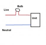
alright, removed the relay and shorted it manually with wire, but what am i supposed to do with the bulb? wire it like pictured?
An externally hosted image should be here but it was not working when we last tested it.
The bulb goes in series with the incoming mains supply to limit current. It goes on the live side like this.
Looking at your picture though, which makes it easier to follow, you could also try unsoldering the two ? pins on the STK that go to that relay and just try powering up normally (without the relay shorted).
What I am trying to establish is whether or not the STK is faulty and drawing excess current which is "killing" the supply. Having seen the picture maybe try that first. Don't have any speakers connected while working on this.
Attachments
you mean these 2 pins right? so put the relay back in, desolder those 2 pins and power up as normal with bulb? k ill do that right now.
An externally hosted image should be here but it was not working when we last tested it.
- Status
- This old topic is closed. If you want to reopen this topic, contact a moderator using the "Report Post" button.
- Home
- Amplifiers
- Solid State
- ideas on fixing amp?