heres the results of what you said to do. and the chip is a STK4172II.
http://www.youtube.com/watch?v=tILBwFjTU4o
http://www.youtube.com/watch?v=tILBwFjTU4o
Forgot to mention...
If it is still the same with all those pins disconnected then do the following.
1. Switch off and check with your DVM that there is no significant voltage on the PCB print to the pins before you resolder them back up. If there were then any short with the iron/solder could cause damage.
2. With it all connected back up fit those two jump links back on to the relay to short the contacts out.
3. Still using the bulb tester power the unit up.
4. Providing there is 0 (zero) volts across the speaker sockets connect a speaker and see if there is any audio.
alright, we seem to be getting somewhere...
desoldering those pins did nothing, but jumping the relay made it work. audio can be heard through my headphones (havent tested speakers yet, just about to) so it seems like something is making the relay open/close strangely like that. also, if it matters, the bulb doesnt dim down like it was earlier, it glows bright and slightly pulsates with the audio (power draw i guess?)
edit: speakers also work too.
Last edited:
That's good, proves it's basically all OK and to be honest that I was on the wrong track suspecting the STK...
Switch off and don't overheat the STK without its heatsink.
Others have mentioned electroylitics... but I think you said you had replaced them all ?
You need to look at the small "auxilliary" standby power supply section. That is the supply that feed the relay and may be little more than a single diode and reservoir cap.
It's quite possible the diode could be defective assuming the cap is OK.
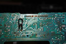
Going to have to just leave it for now but see if you can trace from the relay coil pins back to the supply and diode that feed the relay. Also if you could prove detailed pic of the PCB showing the relay area clearly on both top and bottom of the boards.
Switch off and don't overheat the STK without its heatsink.
Others have mentioned electroylitics... but I think you said you had replaced them all ?
You need to look at the small "auxilliary" standby power supply section. That is the supply that feed the relay and may be little more than a single diode and reservoir cap.
It's quite possible the diode could be defective assuming the cap is OK.
Going to have to just leave it for now but see if you can trace from the relay coil pins back to the supply and diode that feed the relay. Also if you could prove detailed pic of the PCB showing the relay area clearly on both top and bottom of the boards.
i havent replaced every single cap yet, just what i could find at the local electronics store. i replaced all of the bigger high uf caps, and a couple of the smaller -100uf caps. i will be replacing them with higher quality caps like nichicon later if im able to repair the amp. heres the pictures you requested:
An externally hosted image should be here but it was not working when we last tested it.
An externally hosted image should be here but it was not working when we last tested it.
You just removed the speaker output DC protection relay. If the module fails, your speakers will now be at risk of burning.
You should rather find out why the relay is chattering, the most likely cause is as said before the aux power supply the dc protect circuit gets its voltage from.
You should rather find out why the relay is chattering, the most likely cause is as said before the aux power supply the dc protect circuit gets its voltage from.
i seemed to have fixed the chattering relay issue - it was due to cracked solder for the capacitor in the bottom left corner of the picture. so i put the relay back in and started it up, the relay clicked on normally but now there is a background hum not affected by volume. so i tried desoldering the capacitor again and put back the wires to short the relay and now the hum is still there, just much less noticible. i also noticed that the bulb doesnt stay bright like it used to the first time i tried shorting the relay, and that the audio that time was very clear. did i do something from that time to when i tried to take the picture?
I wouldn't worry to much over the bulb... even a very small increase in current can cause the bulb to suddenly glow. It's to do with the resistance of the bulb being very non linear with regard to temperature.
I think you have to carefully build it all back up again. You have found a very definite fault with the cracked print so that should be the only problem really.
I take it when you talk of this hum you mean it's coming from the speakers and not from some component within the amp... just trying to be absolutely clear on whats going on.
oh i see..
and yes the hum is coming from the speakers and not from the amp. but it has since gone away, after i reassembled the unit it was there for a couple of seconds when i was testing but then disappeared after, hasnt show itself since.
thanks everybody who posted for your help and patience! glad i was able to get this fixed!
oh, another question i havent really thought about yet, since the voltage in japan is 100v, and the unit is rated for 100v, is there any problem with using it on americas 120v? i do have a step down transformer but havent been using it because of its large size. is it alright for me to just continue using it as i have been or is there a solution i can make up that i can put inside the unit?
also, another question, why do i have to have the tape deck plugged into the unit to operate it? is there actually something inside the tape deck portion that the amp needs to operate? or is there some way that i can trick the amp into thinking that its connected?
and as for the hum i was talking about earlier, it seems that when i unplug the unit for a couple of minutes then plug it back in the hum will reappear. but it goes away after a couple of seconds. perhaps capacitor related? with the capacitors discharging upon unplugging the unit?
Running it on 120 instead of 100 volts is over running it. All the DC voltages will be around 20% higher than they should be. Whether that's survivable long term I don't know. It may push voltages over the rating of some electroylitic caps working voltage. Power dissipation will be higher in regulators... so they run hotter. Is there not a choice of tappings on the mains transformer for other voltages ?
Tape deck... without knowing the details impossible to say. I couldn't turn up anything on the model number when I looked the other day. If it's all part of a unique stack system rather than true separates then some interdependancy may exist.
Hum... maybe cap related. Maybe related to running on 120volts")
Tape deck... without knowing the details impossible to say. I couldn't turn up anything on the model number when I looked the other day. If it's all part of a unique stack system rather than true separates then some interdependancy may exist.
Hum... maybe cap related. Maybe related to running on 120volts
yes its all part of a unique stack system. only compatible with this amp. and from what i can see, its just wired from the mains to the relay, a couple of resistors then straight to the main power transformer, which then branches off to other things, and to the audio transformer.
If you wanted to post good pics of the mains transformer, then maybe we could tell if it had other voltage options.
In a nutshell though, if the tranny has only two connections or wires actually coming out of it on the primary side then it's fixed. If it has more than two and some are unused then it may well be for different voltages.
In a nutshell though, if the tranny has only two connections or wires actually coming out of it on the primary side then it's fixed. If it has more than two and some are unused then it may well be for different voltages.
An externally hosted image should be here but it was not working when we last tested it.
there seems to be 3 unused leads.
this might be a wild guess, but if this board was pre-preped for US sale as well, maybe the line in blue would be what is jumpered for 120v sale?
An externally hosted image should be here but it was not working when we last tested it.
Last edited:
- Status
- This old topic is closed. If you want to reopen this topic, contact a moderator using the "Report Post" button.
- Home
- Amplifiers
- Solid State
- ideas on fixing amp?