Is this the right way to implement baker clamps? Are there any special requirements of the diodes use?
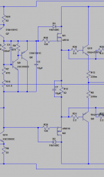
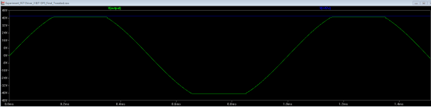
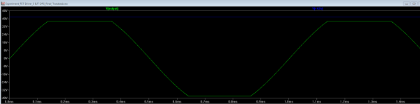
Attached schematic shows the placement of the diodes, attachment 2 shows simulation of clipping without Baker clamps, a small amount of "sticking" is clearly seen. Attachment 3 shows same clipped signal but with Baker clamps incorporated, no "sticking" to be seen.
Guess it works.
Attached schematic shows the placement of the diodes, attachment 2 shows simulation of clipping without Baker clamps, a small amount of "sticking" is clearly seen. Attachment 3 shows same clipped signal but with Baker clamps incorporated, no "sticking" to be seen.
Guess it works.
Attachments
baker clamps only apply to bipolar devices, by which a circuit arrangement is used to prevent transistor BC juctions from turning on ( ie full saturation) usually only used in switching applications non linear. useful for speeding up bipolar switch performance.
If you havent noticed im using bipolars in my output and FET just for drivers.
uhh sorry looking for diodes only
seems special biasing is needed to keep the FET fully turned on during clipping
are the driver supplies Vgs higher/lower than the OP collectors.
Looking at it again it might be better to place the diodes between output of the FET drivers and supply, instead of between VAS output and supply.
EDIT : Well that doesnt work, between VAS output and supply looks like the correct way to do it.
Last edited:
From what I can see you don't need a baker clamp, because the BJTs will never saturate.
IPS-VAS are on 55 V rails, the FET drivers and BJT OPS are on seperate 42 V rails. If you dont limit the output voltage of the FET drivers in some way, the BJT OPS will saturate.
Last edited:
Depending on the actual values of the rails is it not possible that excessive current could flow via the diodes into the rail supplying the outputs (assuming the front end were on a higher voltage) or are Q7 and 14 current limited... can just see a line going off from them. To a B-E junction and current limiter maybe.
If simulation shows them to work the next step is test it for real under real clipping conditions.
If simulation shows them to work the next step is test it for real under real clipping conditions.
Depending on the actual values of the rails is it not possible that excessive current could flow via the diodes into the rail supplying the outputs (assuming the front end were on a higher voltage) or are Q7 and 14 current limited... can just see a line going off from them. To a B-E junction and current limiter maybe.
If simulation shows them to work the next step is test it for real under real clipping conditions.
The diodes only start to conduct when the VAS output voltage is equal to the OPS Supply voltage + one diode drop.
So as long as the VAS output is below 42 V + 0.7 V the diodes will not be conducting. Only in clipping conditions will there be flowing current from the IPS-VAS supply to the OPS supply.
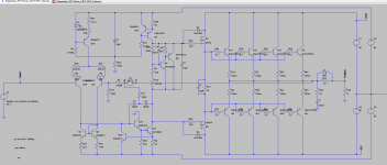
Attached is full schematic.
Attachments
Don't forget to add protection zeners on the MOS devices. The zeners should clamp Vgs to less than 20 V. I generally use 15 V zeners for this.
~Tom
Is that really necessary?
Don't forget to add protection zeners on the MOS devices. The zeners should clamp Vgs to less than 20 V. I generally use 15 V zeners for this.
~Tom
Is that really necessary?
Any particular diode better than others? Would a lowly 1N4004 be good enough? What about Schottky diodes? Do different diode type make any difference?
Zener diode is different from diode.
posts11, 12, 13 &14 are successive.Really?Thats new to me.
Andrew, I was talking about diodes for use as Baker clamps.
it appeared that all are related and discussing the same protection.
If you have changed topic then say so.
posts11, 12, 13 &14 are successive.
it appeared that all are related and discussing the same protection.
If you have changed topic then say so.
Well it could be understood that way, but since he wrote about using ZENERS to protect the FET, why would I be talking about using 1N4004 diodes or schottky diodes?
But was just a little miscommunication, those things happen and life goes on.
- Status
- This old topic is closed. If you want to reopen this topic, contact a moderator using the "Report Post" button.
- Home
- Amplifiers
- Solid State
- Baker clamps?