Niss_man, I have set my bias to 100mA and the sound seems to be improved. This is on a low-NFB amp of my design, just my own experiment. I think, in terms of the end goal of a good sounding amp, that setting the bias halfway between Gm doubling and switching spikes is misguided; because bipolar outputs by nature do not switch smoothly, you are putting the majority of the audio in a weird nonlinear bias region. So I think it should sound better to bias the outputs into deep Gm-doubling, so that it is class A except on music peaks.
However if you wanted to set the bias as low as possible without problems, I would use the method I described.
Because this amp has 3 outputs, the load is shared among them, so each pair would see a 24R load if the amp was connected to an 8R load. So you may even get away with 25mA bias!
- keantoken
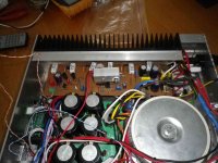
Just been testing my amp. The output emitter resistor voltages seem stable. The only thing I find is the VAS heat sink(in middle of board) gets a bit too hot for my liking. Is it best I make it larger or change the vas emitter resistors?
Regards
Simon
Regards
Simon
Attachments
Could you please explain how to do this in greater detail?What voltage and current is the VAS set to?
Could you please explain how to do this in greater detail?
Read OS's recommendation on the VAS, different R27 gives different VAS current. Beware, changing R27 will have an effect on output bias so start all over again if you change R27.
Just been testing my amp. The output emitter resistor voltages seem stable. The only thing I find is the VAS heat sink(in middle of board) gets a bit too hot for my liking. Is it best I make it larger or change the vas emitter resistors?
Regards
Simon
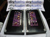
Is it just me and my eyes or are your boards flipped?
I mean, with the board's opt side away from you, the input should be on the right and the power supply on the left...

Attachments

Thanks! Yeah it's been playing hard for hours, connected to an iPod Touch via LOD and a passive pre and the sinks only gets barely warm.
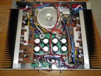
I would have opted for the Vbe on top of one of the opts but me and the guys decided on using a thermal bar. It looks good with the alum bar, very symmetrical.
Yes it's upside down, the opts are on the lower portion of the heatsinks, though in the video, you'll see the opts towards the top to facilitate probing the bias and other stuff.
Read OS's recommendation on the VAS, different R27 gives different VAS current. Beware, changing R27 will have an effect on output bias so start all over again if you change R27.
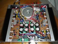
Reading 0.544V across R27(68r) = 8mA.
Yeah my boards are flipped. I accidentally produced my boards as a mirror image so transistors to the heatsink are underneath. Components on top had to be installed as a mirror image.
Regards
Simon
Reading 0.544V across R27(68r) = 8mA.
Yeah my boards are flipped. I accidentally produced my boards as a mirror image so transistors to the heatsink are underneath. Components on top had to be installed as a mirror image.
Regards
Simon
Just about right on the VAS, I'm running our prototype at about ~10mA with 56R for R27. As you can see in the video, after 2 hours it still remains at no more than 47 degrees Centigrade.
I see, I thought my eyes were failing me when I saw the orientation of your pcb.
Cheers
Am happy with VAS now. Changed R27 to 100r and reset the bias adjustment a little lower than before. Also doubled the size of the vas heatsink. Now it runs nice and cool as I like. I have access to one of those laser temperature probes as on your video at work so will use it when I get the oportunity. Thanks for your help.
Regards
Simon
Regards
Simon
Attachments
Back to the same questions
What voltage and current is the VAS set to?
OT: jojo, nice meeting you and Jason finally at the audio show yesterday..... wished we could talk longer, please give my best to Jason....
Great to meet you too Tony
It was a very cool show and awesome to meet you and all the locals Am happy with VAS now. Changed R27 to 100r and reset the bias adjustment a little lower than before. Also doubled the size of the vas heatsink. Now it runs nice and cool as I like. I have access to one of those laser temperature probes as on your video at work so will use it when I get the oportunity. Thanks for your help.
Regards
Simon
Cool. The heat from the VAS is quite constant. The recommended heatsink was more than enough to maintain temps below 50*C even with higher ambient temps. I live in a tropical country so it gets kinda warm during the afternoon.
If anyone has the equipment and know how (of which I have neither)to do this who lives near by to me I would gladly donate my time and amp to help find out. The simple answer I think is Bloody Low distortion and sounds Great....
Regards
Simon
Regards
Simon
I was checking through the thread and it didn't seem like there were any THD-20kHz, IMD, PIM, etc.
Anybody feel like running more sims?
As it relates to the board I am doing for this project, just how long does it take, for those that make their own boards, using the toner transfer method, most of you to "IRON" on the toner? Is there a set period of time to take that does not burn the board paper used in the transfer? Just curious. It seems to take me for ever. In excess of 30 minutes per side.
- Home
- Amplifiers
- Solid State
- diyAB Amp - The "Honey Badger"