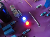
Okay, one other thing. D102 and D103 should be replaced with a red LED, same for D202 and D203. Green LEDs may be necessary, we will just have to see. I use them this way in my K-multipliers and they haven't exploded thus far with 24V rails... This datasheet gives 1A max surge current:
http://www.chml.com/products/pdf/1-78.pdf
Maybe a 470R series resistor would offer adequate protection...
How about input LTP degeneration/offset trimmer? Is that arranged right?
- keantoken
http://www.chml.com/products/pdf/1-78.pdf
Maybe a 470R series resistor would offer adequate protection...
How about input LTP degeneration/offset trimmer? Is that arranged right?
- keantoken
The 100k resistor is chosen to be right on the edge. The base current of the bipolar is several uA. This means there is enough voltage across the 100k resistor to forward bias the diodes. When this happens, the diodes conduct and reduce the filtering capability of the regulator. So choosing a diode with higher breakover voltage will improve filtering. Red LEDs give about 1.8V, green ones give about 2.9V. If green is necessary, then I would rather modify the circuit I guess.
- keantoken
- keantoken
grounding
In this circuit there is a " ground breaker " ( D1-D2-R4 ) and star grounding is on the circuit board betwen C17 - C13.
Should the RCA input connector be connected to amplifier case and amplifier case be earth grounded.
This way amplfier ground is made across ground breaker.
Or should the RCA be insulated from case( as done in LEACH ) and ground of the amplifier be made from the circuit board betwen C13 - C17 to case ?
Krisfr, is it possible you can make the text cut out of the ground plane, instead of having to clear space around it? Seems like something sensible any layout program should be able to do.
D104 and D201 still need to be reversed on the schematic and the board.
It looks to me like the input stage CCS is all foobar'd.
- keantoken
The text on the ground plane is not working like I want it to. I want to do a board today, but my testing does not warrant doing it. The text is not readable on the printable sheet.
Any suggestions?
Attachments
Well, you could remove all the text and add the component numbers by hand in white text to the printout file. I'm surprised your layout software doesn't have a suitable feature.
- keantoken
Great Idea and I forgot that the program has a WHITE layer, so It can work... Details at 11...


Glowing good. Mine are glowing too. A question.
With the fuses removed (using 22r resistors in fuse places) and the bias set to maximum resistance my power supply is showing +- 59v which is great. When bias resistance is decreased to set standby current at the correct voltage (20mv between test points) the power supply drops to around 53v and the lamp (series lamp) begins to glow very dimly?
Should I have this voltage drop?
Regards
Simon
Glowing good. Mine are glowing too. A question.
With the fuses removed (using 22r resistors in fuse places) and the bias set to maximum resistance my power supply is showing +- 59v which is great. When bias resistance is decreased to set standby current at the correct voltage (20mv between test points) the power supply drops to around 53v and the lamp (series lamp) begins to glow very dimly?
Should I have this voltage drop?
Regards
Simon
Hi Simon,
Is the 53V measured after the 22 ohms safety resistors?
6V across those resistors is just about right for about 300mA (100mA per device), however your measured 20mV gives only about ~50mA. I would recommend you also monitor current at your output devices.
Cheers
the bulb tester is a tester to help prevent damage when one makes a mistake.
It is not intended for use when setting up the output bias.
Output bias consumes many watts. Many watts is precisely what the bulb tester does not allow to pass.
Similarly the correct fuses must be in place before setting the Vbias above minimum volts.
Get the equipment wired up safely and properly. Check that all devices are appropriately cool. Check circuit voltages and currents. Remove those dangerous test probes. NOW, REMOVE the bulb tester and start up direct on line. If this blows the mains fuse then you need a soft start not a bigger fuse.
Bias up the amplifier.
Test output voltage. Test again. power off, power on, test again.
Finally attach a cheap disposable speaker and listen to noises/hums/buzzes. This should confirm the earlier test output voltage readings.
How is the right bias current determined?
My default approach is to set the scope in differential mode, and probe the voltage between the input and output of the output stage. Then you can visually judge linearity when driven into a satisfactory load. The best point changes with loading, and low-ohm loads need a higher bias point. For a 4 ohm load I determined 68mA was best, assuming that Gm-doubling is acceptable compared to switching spikes. For multiple-output amps it is probably different.
- keantoken
Ok. Yep it was the bulb tester. Now have it set up as per ostrippers instructions. At 20mv across test points I am getting 10mV across each of the 6 emitter resistors.(50ma per device ). Is this ok?
Also now power supply is rock steady at its supply voltage of 59v. No buzzes hums etc from cheap speaker.
Regards
Simon
Also now power supply is rock steady at its supply voltage of 59v. No buzzes hums etc from cheap speaker.
Regards
Simon
Thanks keantoken. I will be using 8 ohm speakers so I geuss my 50mA per output device is good then.
Regards
Simon
Regards
Simon
How is the right bias current determined?
My default approach is to set the scope in differential mode, and probe the voltage between the input and output of the output stage. Then you can visually judge linearity when driven into a satisfactory load. The best point changes with loading, and low-ohm loads need a higher bias point. For a 4 ohm load I determined 68mA was best, assuming that Gm-doubling is acceptable compared to switching spikes. For multiple-output amps it is probably different.
- keantoken
- Home
- Amplifiers
- Solid State
- diyAB Amp - The "Honey Badger"