http://www.diyaudio.com/forums/atta...46315-class-ab-amp-diyaudio-diya-amp-full.zip
Sorry for errors, that's Q14.15 and now MJE15032/3 though either pair would suit
Sorry for errors, that's Q14.15 and now MJE15032/3 though either pair would suit
http://www.diyaudio.com/forums/atta...46315-class-ab-amp-diyaudio-diya-amp-full.zip
Sorry for errors, that's Q14.15 and now MJE15032/3 though either pair would suit
Q13 I used 2sc3953 transistor as Q13. Thats the transistor in the middle of the heatsink used for temperature compensation I think. I used MJE15032/3 for drivers Q14/15 and the MJE15033(Q15) are the ones that blew as well as some power transistors. I am having the feeling that some of the transistors I bought may have been fake.
Repeet I think I will take you up on your offer. It would be nice to meet a fellow diyer in my same town.
PM sent Repeet
Regards
Simon
Last edited:
Have tested power supply without being connected to amplifier board and I get +ve and -ve 61v rails and bulb is not on. (ok)
When connected to amplifier boards +/-ve 50vdc and bulb is on very very slightly(hardly glowing)?
Theres some issue with my amplifier board somewhere.
What is the best place to start now? Maybe remove the power transistors and driver transistors and see if input bumps back up to 60v?
Edit Just found a shorted Q15 driver transistor.
Another question. Is it ok to use a 2sc3953 transistor as Q13??
Regards
Simon
If driver is shorted I'd guess outputs blown. Replace all outputs and drivers. Use complimentary devices don't mix n match. In the meantime after you've put all new devices in you can then test the old ones hfe etc to determine which are ok and which are not.
It is normal for unloaded trafo voltage to be higher than loaded voltage but ten volts is too much.
It is normal for unloaded trafo voltage to be higher than loaded voltage but ten volts is too much.
...also use a lower wattage lamp initially for the lamp tester, e.g. 40 W, to get more than a 'hardly glow'.
(The voltage drop will be even more than 10 V with the lower wattage lamp, but that is the idea).
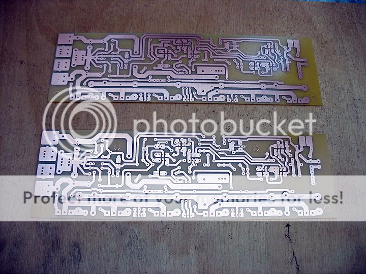
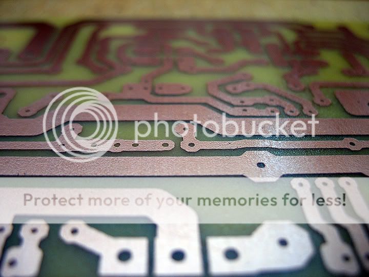
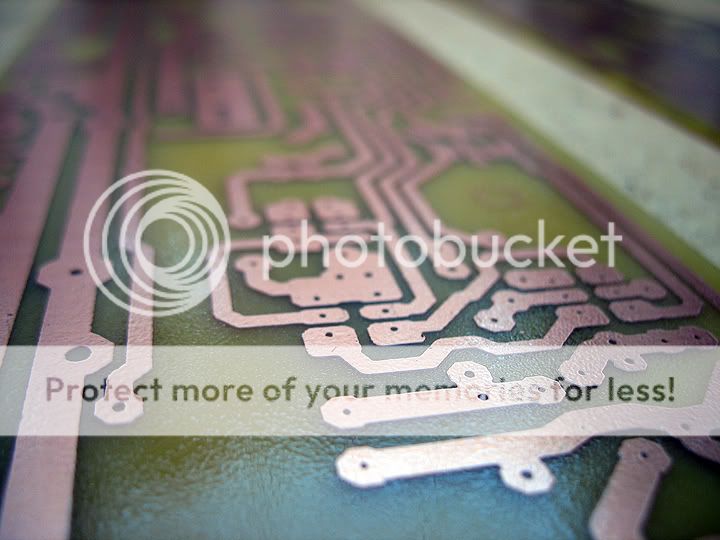
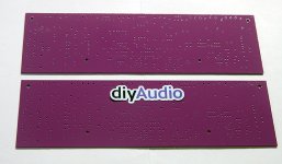
diyAudio Central, in the person of JojoD818 has made an etched pair of boards and will do a test build. When he confirms that it works well, we'll get on with the order. After sending in the order it takes about 6 weeks to get in the store.
I've checked the board against the schematic and all seems where they should be, unless something slipped my tired eyes.
Anyway, like Variac said, I've started making preparations for a test build of this amp. Will post pics of the board soon... Drilling holes tomorrow, most part I hate when doing PCBs...
Let's hope you don't get the same failure I experienced after putting one of these together jojo.
Regards
Simon
I hope so too. Are you rebuilding yours?

Yes I will be shortly. A local member is going to help me out with some new parts.I hope so too. Are you rebuilding yours?
Simon
Yes I will be shortly. A local member is going to help me out with some new parts.
Simon
Great, you should also be meticulous on your device selection, maybe source it from someone you trust.
I have, on many occasions witnessed catastrophic failures all due to fake/counterfeit devices.

I'm the person providing the devices for niss_man.
The drivers are direct from OnSemi and all the others are from Mouser using Ostrippers preferred devices. The only ones I don't have spare are the output transistors.
All parts are genuine. (no ebay parts ever again).
I've gone back to my Greg Ball SKA amp now, and am preferring it over the Mongrel with my newly completed Mini Statement speakers.
I'll probably convert my Mongrel amp to this one once the diyAudio boards become available (even though I told myself no more amps!).
I was never totally happy with my etched boards and the seperate voltage boards on the Mongrel amp takes up a lot of space.
Looking forward to meeting a fellow DIY'er on the weekend.
Pete
Hi Pete,
Glad to hear you guys get your parts from reputable sources. Now I wonder what really went wrong with niss_man's amp...
I have a pair of boards running. They are my own layout, but using the same basic circuit.
No music yet, but they measure great.
The one failure I had was my own doing - thermal runaway on one power PNP due to mangled threads on the heat sink (broken tap on last hole...).
Moral of the story:
Carefully check the voltage drop across each 0.22 ohm resistor at first power up, after adjusting the bias. Turn off asap if any do not stabilize or if significantly higher than the others.
Build and assemble and power up using a method that prevents destruction in event of a wiring error or a component failure.
jojod is a seasoned veteran with builds exceeding yours by more than 20 times, i am sure he knows what he is doing....
Let's hope you don't get the same failure I experienced after putting one of these together
jojod does not seem to be the specific target for my comment.jojod is a seasoned veteran ................................ I am sure he knows what he is doing....
Nissman needs it more.
But my comment was not targeted at any Member in particular. It is general advice to all Members.
I make mistakes too.
Mostly at the measurement stage where a probe slips and shorts across a connection. Disaster generally. I do wish there was the habit of including test loops in the Group Buy PCBs, but this is rarely if ever seen.
I have occasionally misplaced NPN for PNP. This type of error is generally caught with the bulb tester. Similarly swapping polarities can be caught with the bulb tester.
I have a pair of boards running. They are my own layout, but using the same basic circuit.
No music yet, but they measure great.
The one failure I had was my own doing - thermal runaway on one power PNP due to mangled threads on the heat sink (broken tap on last hole...).
Moral of the story:
Carefully check the voltage drop across each 0.22 ohm resistor at first power up, after adjusting the bias. Turn off asap if any do not stabilize or if significantly higher than the others.
Cool, I have checked the board against the schematic several times and so far so good that's why it's a go. I just hope my eye hasn't failed me.
That failure could had been easily fixed by adding an aluminum thermal bar across all the outputs.
jojod does not seem to be the specific target for my comment.
Nissman needs it more.
But my comment was not targeted at any Member in particular. It is general advice to all Members.
I make mistakes too.
Mostly at the measurement stage where a probe slips and shorts across a connection. Disaster generally. I do wish there was the habit of including test loops in the Group Buy PCBs, but this is rarely if ever seen.
I have occasionally misplaced NPN for PNP. This type of error is generally caught with the bulb tester. Similarly swapping polarities can be caught with the bulb tester.
There can be a number of mistakes in an amp build especially if ones mind is somewhere else during the build, concentration is somewhat essential.
It has been my personal procedure to check and re-check all wiring and device orientation before I power up.
Another safety advise would be to always, always power up when you and your work are good and ready.
jojod is a seasoned veteran with builds exceeding yours by more than 20 times, i am sure he knows what he is doing....
hi tony, it seems it has been a life-long passion for me...
- Home
- Amplifiers
- Solid State
- diyAB Amp - The "Honey Badger"