Hi Tony,
Well, it depends on whether it's the classical definition of class A that is applied, or one of the more modern "does the same thing" type of definitions.
In truth, true class A designs have their issues, as do the quasi class A designs and class A-B designs. Personally, I'll take the class A-B type designs over a classical class A design. Beyond that, "it depends" would be the answer. Those line blurring quasi class a designs can have their issues too. They don't always deliver on the promise either and tend to be more twitchy with various devices (transistors I'm thinking here).
Better transformers. Might they show up a poor design rather than hide it behind their own shortcomings? Today we have much better average control over purity of metallic components and wire. Same for dimensional factors, but after seeing what they were able to do I will not sell early transformers short. I think they were able to produce as good a transformer as we do now. It's just the predictive design tools we have now that have changed. Like everything, quality and performance pretty much depended on how much money was behind the effort.
You wind your own transformers whereas I don't, never have and doubtful that I ever will. What are your thoughts on this?
-Chris
I may have confused every on the test that is wacko it is the bias test all I get when measuring between tp1 and tp2 is 4 milli volts regardless how many turns I make on r 30. I checked r30 and reset it to 500 ohms so as I turn it counter clockwise to decrease resistance readings go from 0 to 4 milli volts. Thank you all for the help
I may have confused every on the test that is wacko it is the bias test all I get when measuring between tp1 and tp2 is 4 milli volts regardless how many turns I make on r 30. I checked r30 and reset it to 500 ohms so as I turn it counter clockwise to decrease resistance readings go from 0 to 4 milli volts. Thank you all for the help
It sounds like you have low VAS current. When I get a few minutes I'll figure out how to check it and report back.
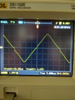
So latest update still running 4 to 8 milli volt bias but I installed speakers and fuses It plays music but there is an idle hum or buzz and seems a bit distorted as I up the volume at full volume into a 4 ohm 30 watt speaker it is not real loud but you can see some cone movement at the rubber surrounds
This is the output on a dummy load.Thimios, is that scope connected from speaker output to ground or VAS stage to ground.
VAS to ground would show the correction signal.
One last question on my smoked HB amp I did manage to get some bad grade music out and noticed that heat output seems near zero even after 10 min of music? also while doing pretest checks if I touched heatsinks to steady my hand the millivolts would bounce all over the place? Ordered new boards and parts seemed easier and quicker(most parts on hand). Thank you all for keeping the hobby going
Hello Tony,
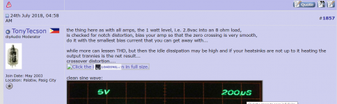
Could you attach the images to post . I am not able to open and see the first image. I don't know why. Post no. 1857
Regards
Prasi
not sure what you are asking...
Hi Tony,
Well, it depends on whether it's the classical definition of class A that is applied, or one of the more modern "does the same thing" type of definitions.
In truth, true class A designs have their issues, as do the quasi class A designs and class A-B designs. Personally, I'll take the class A-B type designs over a classical class A design. Beyond that, "it depends" would be the answer. Those line blurring quasi class a designs can have their issues too. They don't always deliver on the promise either and tend to be more twitchy with various devices (transistors I'm thinking here).
Better transformers. Might they show up a poor design rather than hide it behind their own shortcomings? Today we have much better average control over purity of metallic components and wire. Same for dimensional factors, but after seeing what they were able to do I will not sell early transformers short. I think they were able to produce as good a transformer as we do now. It's just the predictive design tools we have now that have changed. Like everything, quality and performance pretty much depended on how much money was behind the effort.
You wind your own transformers whereas I don't, never have and doubtful that I ever will. What are your thoughts on this?
-Chris
better transformers than what can be found in commercial amps...
in terms of heating perhaps if that is the goal..
diyers are free to choose how big or small the traffos that they will use...
Rock12, look at the silkscreen orientation for r30, then look at the solder pads on the bottom of the pcb. You will see that two of the leads from r30 are connected to each other by the pads. Take r30 and measure from the single lead and the two connected leads. Turn the screw in the direction that increases the resistance until max resistance is reached, probably between 470 to 500 ohms, then install r30 as shown by the silkscreen. Turn the screw the opposite direction to adjust bias. It might take a number of turns before you see the millivolts start to rise as you turn the screw.
not sure what you are asking...
the first link in the post #1857 doesn't load for me.
it does the "loading...loading...." thing all day long, without actually loading any image..

screenshot attached.
Attachments
- Home
- Amplifiers
- Solid State
- diyAB Amp - The "Honey Badger"