I found it.
I can't open the file Badger_V2. silk.pdf. Is the file broken? Also, I believe the traces for the other side of the PCB are missing.
Wouldn't it be better to have the full (pre-PDF) files available so we could send these out to a manufacturer and get finished boards with drilled holes and all?
what software to open that .lay file?
That's a Sprint file.
draw out your LTP+source resistors, with the two voltages @ +IN & -IN.
Measure the Vgs of both halves.
Mark that on your sketch.
Measure the Vdrop across each Source resistor.
Mark that on your sketch.
Does that all add up?
BTW,
The k170 datasheet shows ~180mVgs for a 6.2mA Idss device operating @ 2mA.
What should your Vgs be for your devices at your currents?
Built the second board.... this time is even worst, offset near 0.7V and heavy oscilation (11VAC at 400khz)
Tryed changing the drivers but did not cure it.
I am really sad about this
Why don't you start with the standard Honey Badger design (which is known to work well), and then start modifying this towards your liking? This might make it easier to understand where/why you get oscillation and DC offset.Interestingly it does oscilate even if I disconnect the output devices so oscilation is on the driver stage.... will try to increase base stoppers
Built the second board.... this time is even worst, offset near 0.7V and heavy oscilation (11VAC at 400khz)
Tryed changing the drivers but did not cure it.
I am really sad about this
did you try adjusting tail currents?
did you try adjusting tail currents?
Yes, increasing big ccs current slightly reduces offset but only slightly, from .3 to .25v
- Home
- Amplifiers
- Solid State
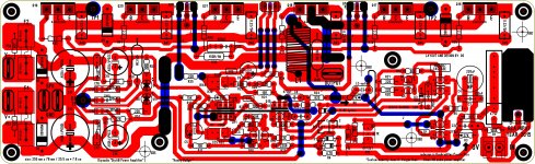
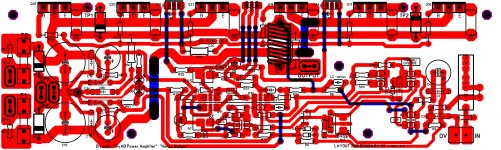
- diyAB Amp - The "Honey Badger"