The HB PCBs are sold out in the diyAudio store. Will there be a new batch? I wouldn't mind getting some more...
Also, if there will be a next batch, I'd suggest to drill the hole a little bit larger. I had a hard time to fit most resistors (I used Dale CMF55) and some other parts.
Also, if there will be a next batch, I'd suggest to drill the hole a little bit larger. I had a hard time to fit most resistors (I used Dale CMF55) and some other parts.
Hi!
I have looked around and searched many of the badger threads for several days, but i cant find the latest BOM.
I'm in the planning stage, calculating the costs.
I'm thinking about maybee build a bi-amp set of total four amp modules, 2 cases with 2transformers. It would be like 2 stereo pairs, but set for bi-amping only.
My speakers are Yamaha Soavo 1. 6ohms 89db i think.
Do you think i would need 2 or 4 "universal psu boards". If i use 4 psu boards for 2 transformers, what kind of VA range should IT be, and something like 40-0-40v. I'm thinking the rails could be 4x10000uf and 4x 4700uf or so..
I want the best audio quality and not max power, but i dont want it to be to complicated. It would be my first amp build.
Thank you!
Mattias
Hi!
I have looked around and searched many of the badger threads for several days, but i cant find the latest BOM.
I'm in the planning stage, calculating the costs.
I'm thinking about maybee build a bi-amp set of total four amp modules, 2 cases with 2transformers. It would be like 2 stereo pairs, but set for bi-amping only.
My speakers are Yamaha Soavo 1. 6ohms 89db i think.
Do you think i would need 2 or 4 "universal psu boards". If i use 4 psu boards for 2 transformers, what kind of VA range should IT be, and something like 40-0-40v. I'm thinking the rails could be 4x10000uf and 4x 4700uf or so..
I want the best audio quality and not max power, but i dont want it to be to complicated. It would be my first amp build.
Thank you!
Mattias
That sounds pretty familar to me
") I found it rather difficult to chase down all the changes and new options introduced since the (outdated!) diyAudio build guide was released for the Honey Badger version 2.0 (or so?). The diyAudio store has a schematic labelled version 2.4, which shows different parts/values than those in the build guide, but there are no explanations for the changes. I considered starting a thread focusing on the changes and options involved in the Honey Badger, making things a bit easier. However, I think the "thread format" is not the best for this. A WIKI style document that can be edited by everyone would be much easier to maintain than a yet another confusing thread getting longer and longer (but I don't know how/where to do that). In the meantime, I could send you the parts list for my builds (let me know if interested).
I found it rather difficult to chase down all the changes and new options introduced since the (outdated!) diyAudio build guide was released for the Honey Badger version 2.0 (or so?). The diyAudio store has a schematic labelled version 2.4, which shows different parts/values than those in the build guide, but there are no explanations for the changes. I considered starting a thread focusing on the changes and options involved in the Honey Badger, making things a bit easier. However, I think the "thread format" is not the best for this. A WIKI style document that can be edited by everyone would be much easier to maintain than a yet another confusing thread getting longer and longer (but I don't know how/where to do that). In the meantime, I could send you the parts list for my builds (let me know if interested).Hi!
I have looked around and searched many of the badger threads for several days, but i cant find the latest BOM.
I have started a Wiki page for the Honey Badger. I put my BOM there.
I hope the Wiki page may serve as a better place for the community to maintain a central repository for the changes and options involved in the Honey Badger design.
I have started a Wiki page for the Honey Badger. I put my BOM there.
I hope the Wiki page may serve as a better place for the community to maintain a central repository for the changes and options involved in the Honey Badger design.
Exellent work!
I calculated my buildcost and it looks like it's closer to 2000€.
I think i wait with the build.
Exellent work!
I calculated my buildcost and it looks like it's closer to 2000€.
I think i wait with the build.
Rip the transformer and heat sink from an e-waste amp, then you can reduce the parts cost a lot. I just built a 2p slewmaster (roughly the same part count as the HB) for ~1000 nok using transformer and psu caps from a HK690 I found in the e-waste.
You can reduce costs further by using e-waste chassis. Surround receivers are perfect size.
$2000 sounds very expensive anyway. I spent around 6000 nok when I built my HB as my first diy project I bought extra of most components for future projects
http://www.hifisentralen.no/forumet...e-bygger-honey-badger-og-annet-sma-tteri.html
Last edited:
Rip the transformer and heat sink from an e-waste amp, then you can reduce the parts cost a lot. I just built a 2p slewmaster (roughly the same part count as the HB) for ~1000 nok using transformer and psu caps from a HK690 I found in the e-waste.
You can reduce costs further by using e-waste chassis. Surround receivers are perfect size.
I plan on building an e-waste badger/ or slewmaster once my current HB is finished. It is proving to be a difficult task to get e-waste around Newfoundland though!
I plan on building an e-waste badger/ or slewmaster once my current HB is finished. It is proving to be a difficult task to get e-waste around Newfoundland though!
It's difficult to get e-waste in Norway too. In the junk yards you are not allowed to take anything. All Electronic shops have e-waste outside, but it's illegal to take anything there. When recycling a washing machine, I saw the HK690 in a pile. I looked around to make sure no one was watching and suddenly the hk690 fell into my trunk.
Hey Guys!
I have listened to your advices, I have bought the MJL4032/4281 OP transistors!
While building, I got a question (please don't kill me, as I'm not that good at electronics):
Do I have to connect the ground of the power lines to the chassis?
The problem is: I want to use a balanced input, with the reciever THAT 1206. As I don't have the voltage needed for the reciever, I have to use a second transformer, providing a clean dual 12V (yeah, I know, I wrote +-15V on the paper...)
I made a quick drawing how I imagine connecting everything together, please help me if I'm wrong, and would make hum.
So on the attachment, you can see that I instantly connect the earth of the power plug to the chassis, as well as the XLR pin 1, as advised in the THAT 1200 series datasheet. The power plug powers two transformers connected in parallel: the big 1000VA one for my babies, and the smaller one for the THAT circuit. Both go into their respective PSU, the bigger one uses the Universal PSU, the smaller uses a custom made using 7812 and 7912. The XLR balanced signal connects to the reciever which makes it unbalanced, and it provides the signal to the honey badger. the universal psu connects to the badger aswell, and the magic happens in there and I get an output signal from the amplifier.
The only chassis wires are the power plug earth and the XLR pin 1's? Or am I missing something?
Thanks for the help in advance!
Attachments
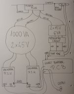
That looks all OK.
The chassis at both ends of the balanced impedance interconnect get attached to the screen via Pin1.
If you have two XLR inputs you end up with two interchassis connections. That lowers the impedance of the interchassis connection and that is a good solution. (H.Ott).
Inside your amp box, you have Pin1 connected to chassis and PE connected to Chassis.
All of the audio is not connected to Chassis.
You need to look at your final assembly and decide whether you have any exposed conductive parts. If you have, then these should be connected to the protected chassis.
This is not an audio requirement. The amp works perfectly well without any audio to chassis connections. This is a Safety requirement.
I see a spare 0V on the left side PSU.
You could use this to make that Safety connection to protected Chassis.
Is there an interwinding screen in your mains transformer/s?
Last edited:
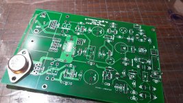
Just built this rig and have got 0.3v output offset.
Can not reduce it without seriously degrading LPT balance.
What should be the cause for a so high output offset ?
The input transistors are very well matched.
Please advise
PS: Appart from the offset, all voltages seem correct and the amplifier works into a 10ohm load fed with a sin signal and viewed on the scope.... promising
is the input jFET or BJT?
what have you actually assembled?
It is the jfet input ltp that uses very well matched lsk devices
- Home
- Amplifiers
- Solid State
- diyAB Amp - The "Honey Badger"