Hey OS, there are some things I thought I should ask you about.
1: Badger current mirror transistors. Maybe I'm too late with this, but I thought we wanted to use better transistors for the current mirror, since the KSA992 is at a disadvantage here:
http://www.diyaudio.com/forums/solid-state/192431-diyab-amp-honey-badger.html#post3196905
http://www.diyaudio.com/forums/solid-state/192431-diyab-amp-honey-badger.html#post3312987
http://www.diyaudio.com/forums/solid-state/192431-diyab-amp-honey-badger.html#post3331999
And, did you ever try the CM choke? If only to see how many mV of SMPS noise your computer generates?
http://www.diyaudio.com/forums/solid-state/192431-diyab-amp-honey-badger.html#post3588483
And I remember long ago you like to use MJL outputs from different power grades because they matched well, but I don't know if that's still true:
http://www.diyaudio.com/forums/solid-state/192431-diyab-amp-honey-badger.html#post3588483
The "Badger" is an "open ended" design.
CM can be any BCE ... KSA1015 is perfect as a 992 replacement. Mouser
has 20K of these at .43$.
I designed the input pair to be EBC .... about 20 devices from mouser could
work. Any of the BCxxx would work (they would be "back to back").
The Zetex line would be perfect (lower voltage - expensive).
Fairchild (SS8550 , MPSAxxx , many others) Differential degeneration
could be tweaked for best performance.
And you could just use the good ol' ksc1845 ... the amp would still be
wonderful.
I am quite pleased that this design has had no real issues considering the
many parts the builders have been using. Still4given used MJE340/350 for
VAS .... all is well.
We can refine the choices to get a little better performance. I personally
use the KSA1015") for CM and the SS9014 (c grade) as input pair.
for CM and the SS9014 (c grade) as input pair.
ksc1845 for cascode , of course ...
Glad to see you back , Keen.
OS
CM can be any BCE ... KSA1015 is perfect as a 992 replacement. Mouser
has 20K of these at .43$.
I designed the input pair to be EBC .... about 20 devices from mouser could
work. Any of the BCxxx would work (they would be "back to back").
The Zetex line would be perfect (lower voltage - expensive).
Fairchild (SS8550 , MPSAxxx , many others) Differential degeneration
could be tweaked for best performance.
And you could just use the good ol' ksc1845 ... the amp would still be
wonderful.
I am quite pleased that this design has had no real issues considering the
many parts the builders have been using. Still4given used MJE340/350 for
VAS .... all is well.
We can refine the choices to get a little better performance. I personally
use the KSA1015
for CM and the SS9014 (c grade) as input pair.ksc1845 for cascode , of course ...
Glad to see you back , Keen.
OS
i used the SS9014, did not grade it and output offset was quite low, i did not even touch the offset adjustment on the board after i set it to center...
did not use the mje340/350 and used the recommended trannies and pot settings, i was satisfied with the results after power on that i never even bothered to make adjustments...
did not use the mje340/350 and used the recommended trannies and pot settings, i was satisfied with the results after power on that i never even bothered to make adjustments...
By Keentoken-And, did you ever try the CM choke? If only to see how many mV of SMPS noise your computer generates?
Nope , but you will. A pair of Badger boards are yours ! PM me....
My sub amp will ultimately be "wolverine" or CFA based as will be my
second house amp .... triple based and modular .
I like my V2.3 badger's , but I want a little variety.
I now have my amps sitting behind an optically buffered DAC !
Your input and simulation skills have been very valuable to me , keen.
I even search the forum for some of your material .
OS
You guys have got me thinking. I used MPSA06 for the front end because I had a bunch on hand that were already matched. I think my rails are ±77V. I need to pull things apart eventually to add the diode fix. Should I replace the A06 with mpas18 while I'm in there? I just noticed how much lower voltage they are.
Thanks' Terryy
Thanks' Terryy
Last edited:
You guys have got me thinking. I used MPSA06 for the front end because I had a bunch on hand that were already matched. I think my rails are ±77V. I need to pull things apart eventually to add the diode fix. Should I replace the A06 with mpas18 while I'm in there? I just noticed how much lower voltage they are.
Thanks' Terryy
Both the CM and the input pair can be VERY low voltage , thanks to the cascode.
Keen's suggestion of a lower vsat CM pair (ksa1015), would go the furthest for increased
performance ... more so than the input pair swap.
The CM's precision is one of the major reasons for the badger's PPM performance.
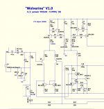
As far as the diode fix , I advanced this design with my new "wolverine" .
What I found was my original advice to increase the TMC feedback R to
1.5K. This will eliminate any ringing at clip or exposure to squarewaves.
Adding the BAV will produce non-ringing, (almost) symmetrical clipping.
Another "finding" ...is that the VAS CCS tries real hard to compensate for
saturation in the active VAS, even if it is active or diode clamped.
. It tries so hard ... that it also saturates to
a lesser degree. Increase the current available to the "backend" of this CCS
and it will exhibit much better behavior. R13 =10K R12=6.8k and a larger C5
will "strengthen" this CCS.
The only better solution would be to separate the references for the 2 CCS's
(2 resistive dividers and 2 caps) ... I did this on the "wolverine" , might
make for a good V2.5 !!
As is , the badger works very well ... these "adjustments" will just make it
more "idiot proof" and party friendly.
OS
Last edited:
The "lowdown" on the clamp.
I simulated the BAV21 , various 1Nxxxx's ....
Any "low reverse leakage" diode ( as specified by the device sheet), will plot at
100's of pA to low single digit nA with low to moderate input signal.
At full throttle , the better ones (the BAV) will show 200nA right before clipping.
The simulated THD will exceed .001% at this point.
The effect on THD is directly proportional to the leakage as compared to the
(2-3)uA of the beta enhancement transistor (Q9). At a certain point - above 500nA,
NFB has a harder time compensating for this "leakage" error.
The lower leakage devices tend to stay in this state (lower leakage) right up
to clipping. Cheap diodes have greater leakage at very low input levels - quite
unsuitable for this application.
Now ... the diode is still an option , If one uses 70V rails and never approaches
clipping .... they might not need it.
OK , janutz ... (below) is most likely V2.5 ... You have it right - split the
CCS references. Active clamp is also the "way to go" .
PS - even with these improvements, the THD is already so low in
the "badger" .... I was only able to shave a few PPM off . Even with a EF3 OPS.
In fact , using the lower Vsat KSA1015 as CM might allow a badger to
do better than the version below .... every component counts !
OS
I simulated the BAV21 , various 1Nxxxx's ....
Any "low reverse leakage" diode ( as specified by the device sheet), will plot at
100's of pA to low single digit nA with low to moderate input signal.
At full throttle , the better ones (the BAV) will show 200nA right before clipping.
The simulated THD will exceed .001% at this point.
The effect on THD is directly proportional to the leakage as compared to the
(2-3)uA of the beta enhancement transistor (Q9). At a certain point - above 500nA,
NFB has a harder time compensating for this "leakage" error.
The lower leakage devices tend to stay in this state (lower leakage) right up
to clipping. Cheap diodes have greater leakage at very low input levels - quite
unsuitable for this application.
Now ... the diode is still an option , If one uses 70V rails and never approaches
clipping .... they might not need it.
What about R11=R12=R13=6k8, C5=68-100uF plus another 47-68uF cap across CE of Q8 or rail and R11 resistor /collector side of Q8 on the back side of pcb?
OK , janutz ... (below) is most likely V2.5 ... You have it right - split the
CCS references. Active clamp is also the "way to go"
.PS - even with these improvements, the THD is already so low in
the "badger" .... I was only able to shave a few PPM off . Even with a EF3 OPS.
In fact , using the lower Vsat KSA1015 as CM might allow a badger to
do better than the version below .... every component counts !
OS
Attachments
A little worse than the BAV , reverse voltage is just enough
(higher would be better).
The 333 variant seems to be better rated (reverse leakage).
OS
Thanks ostripper.
In my first module I'll only change R12 and R13 to 6.8k and possibly solder 10-22uF cap to the other side of the board acros CE of Q8. In the next module I'll start to think how to apply wolverine solution without cutting paths.
For Q5-6 I'm using KSA1015Y, for Q8 I'm using KSC1815Y, Q7=2sc2240bl, Q9=2sa970bl (Hfe=450) while Q10-12 are 2sa1209/c2911s. Q13=ksc2690Ay.
What about diodes such as: bas45a and mmbd1501? How these compare to BAV21?
I'm using 500VA 2x45 toroids with double bridge CRC PS and 3x15mF/80V panasonic caps per rail so my PS voltage will be about +/-63V. Each box will have one toroid and two modules but they will form one channel of an active system working from 80Hz up. Below is an active sub.
cheers,
PS how many MUR860 diodes in series across R in CRC PS? Will one do or two are needed?
Last edited:
Thanks ostripper.
In my first module I'll only change R12 and R13 to 6.8k and possibly solder 10-22uF cap to the other side of the board acros CE of Q8. In the next module I'll start to think how to apply wolverine solution without cutting paths.
For Q5-6 I'm using KSA1015Y, for Q8 I'm using KSC1815Y, Q7=2sc2240bl, Q9=2sa970bl (Hfe=450) while Q10-12 are 2sa1209/c2911s. Q13=ksc2690Ay.
What about diodes such as: bas45a and mmbd1501? How these compare to BAV21?
I'm using 500VA 2x45 toroids with double bridge CRC PS and 3x15mF/80V panasonic caps per rail so my PS voltage will be about +/-63V. Each box will have one toroid and two modules but they will form one channel of an active system working from 80Hz up. Below is an active sub.
cheers,
PS how many MUR860 diodes in series across R in CRC PS? Will one do or two are needed?
Bas45 , according to fig. 5 in it's datasheet ... http://www.nxp.com/documents/data_sheet/BAS45A.pdf
is the best I've seen !
The mmbd1501 .... so-so
... uA , not like the BAS (1nA at 25c !). As far as the CRC , 2 MUR's in series should do.
This depends on how MUCH you want your rails to "sag" in CRC "mode" before the Vf of the diodes kick in.
With .47R between the C's ,a couple of amps will need to be drawn before
this happens. Your "first watt" (and maybe quite a few more )will be behind
a CRC. Higher power will flow through the diodes.
The only thing that works better than this technique is a fully separate
boosted rail for the IPS ... (and/or cap multipliers).
I've also added this (boosted + multipliers) to the "wolverine". All this will
give 120db PSRR ... nearly dual mono with a single supply.
OS
Will this protection circuit impair amplifier sound quality?
Of course it will reduce output power the limit should be at 10 amps &110 volts.
That circuit will just "sit there and mind it's own business" until Re voltage
is greater than a set point.
It's an audio fallacy to say that quality would be degraded. Instantaneous
headroom could be slightly affected , but that "headroom" would most likely
be clipped or distorted regardless !!
The "better way" I prefer , is to monitor those output Re's -
trigger a protection IC/SS relay....
OS
I did know about output stage protection, impedance in that area are low, protection circuit will do no harm.
The protection in VAS stage is a very different situation, I put an extra transistor to limit current to 20 mA in Q10, an extra feature needed if output protection get in action, but an extra capacitance an extra leakage around Q9 & Q10 could be critical, will the extra transistor in VAS cause problems ?
Q12 dont need any protection it is a current source.
- Home
- Amplifiers
- Solid State
- diyAB Amp - The "Honey Badger"