Audiophile caps......
I keep seeing these humongous input caps in the builds.
Perhaps , I could better accommodate them for the V2.4 PCB.
Give me links to the most common ones.
Also , C4 is also a candidate for
"audiophile" status. I will at least make it multipitch and give it more room.
OS
I keep seeing these humongous input caps in the builds.
Perhaps , I could better accommodate them for the V2.4 PCB.
Give me links to the most common ones.
Also , C4 is also a candidate for
"audiophile" status. I will at least make it multipitch and give it more room.
OS
So am I jumper C-Z/C-R ,zener diode replace R18?He did not jumper C-Z/C-R , the cascode reference is "floating".
Jumpering all the small signal traces was not necessary , jumpering the rail traces is optimal.
OS
What a jumper is not necessary?

Got most of the board stuffed and realized I missed ordering some parts that I though were in my parts bin but weren't. So two questions:
How critical is the LTP bias? Can I just replace R7 with 68 75 or 86R? Rough calculation says 68R should be very close to 3.75 mA.
Can I use a 20V Zener in place of R18 without changing anything in the CCS?
Speaking of the cascode, on my boards there was solder mask on the pads. Not a big deal to scrape it off but maybe the next version could have unmasked pads.
Thanks for the fun, OS! Getting close to a Leach vs. Honey Badger shoot out.
In case it affects the answers, I will be running ~62V rails or maybe regulated 65V. 3
TIA,
Bob
Bob,
Your Zener question was addressed in the build thread:
http://http://www.diyaudio.com/forums/solid-state/211905-diyab-amp-honey-badger-build-thread-52.html
Jason
Last edited:
Got most of the board stuffed and realized I missed ordering some parts that I though were in my parts bin but weren't. So two questions:
How critical is the LTP bias? Can I just replace R7 with 68 75 or 86R? Rough calculation says 68R should be very close to 3.75 mA.
Can I use a 20V Zener in place of R18 without changing anything in the CCS?
Speaking of the cascode, on my boards there was solder mask on the pads. Not a big deal to scrape it off but maybe the next version could have unmasked pads.
Thanks for the fun, OS! Getting close to a Leach vs. Honey Badger shoot out.
R7 on Spice (too lazy to open my amp
) ... says 5.60mA for 70R and3.70mA for 65R (68R would be fine...). I settled on 3.75ma both by listening /simulation with
a pair of KSC1845's as the LTP components.
It was discussed that different transistor pairs exhibit different gm characteristics with Ic (current ) being a factor.
Different input pairs also have different "sweet spots" in current ,
the SS9014 "likes" a little less current <3ma . I also saw a reduction in THD20 while using it's model.
A 20V zener is perfect. Most low Vce devices are at 30-40V , you would still have many choices.
Solder mask on the cascode pads ?? Even my original submission had unmasked pads. Maybe the manufacturer ??
My Version 2.3's have unmasked pads ?
OS
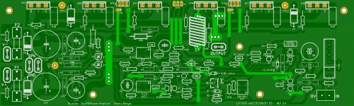
Changed C5/8 , R23/27 , better labeling.
C5/8 (current source cap and Vbe cap) are now 3.5/5mm multi-pitch with
more clearance.
R23/27 (main VAS emitter resistors) are also 12.5/15mm multipitch.
Made [C-Z] the default jumper for the cascode. Also listed R18/22k = C-R as
an option on the silkscreen. The 12V zener is default.
STILL , asking if anyone wants more clearance for C4 and C1.
I have noticed some use high grade components here.
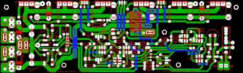
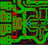
(Below 1 and 2) is the present output.
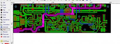
PS - The last attachment is a show of the "test" function on Sprint layout. All
through-hole traces test 100%. (example of the positive rail in pink).
Also , these attachments are 254 X 76 mm - they can be printed out to
see if the holes line up with the DIYA universal layout .
OS
C5/8 (current source cap and Vbe cap) are now 3.5/5mm multi-pitch with
more clearance.
R23/27 (main VAS emitter resistors) are also 12.5/15mm multipitch.
Made [C-Z] the default jumper for the cascode. Also listed R18/22k = C-R as
an option on the silkscreen. The 12V zener is default.
STILL , asking
if anyone wants more clearance for C4 and C1.I have noticed some use high grade components here.
(Below 1 and 2) is the present output.
PS - The last attachment is a show of the "test" function on Sprint layout. All
through-hole traces test 100%. (example of the positive rail in pink).
Also , these attachments are 254 X 76 mm - they can be printed out to
see if the holes line up with the DIYA universal layout .
OS
Attachments
Last edited:
Thanks, OS. For now I'll just use 68R for now, we'll see if I feel like playing with it later. I've got MPSA18s with hfe 580 in the LTP.
The maksed pads were the CRZ jumper pads. Sorry I wasn't clear. The boards are from this August's Rev 2.3 batch.
Yes, just scrape them and jump ... (C-Z) in your case. V2.4 has this issue solved.
OS
HB options
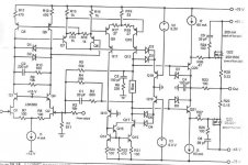
Actually, contrary to some previous comments. I would like to see more options if possible. One of these is preventing saturation of LTP as an option.
Some time ago I attached a diagram of Stochino's amp with anti saturation diodes in LTP and VAS. This time it's taken from Bob Cordell's book. It does not matter that on this diagram Q1 and Q2 are jfets. Apart from what is shown, adding two diodes (both ways) between bases of q1 and q2 Bjts in HB should also prevent these two transistors from saturating although doing that for mirror-cascode is more important.
When it comes to the actual board I would shift C13, C12 and C11 by 7-8mm to the right as I prefer using block terminals and C13 prevents that. As I have V2.3 I'll have to place C13 under the board, which is not so convenient.
When it comes to documentation I'd like to see a diagram with all the DC voltages marked say for +/-60V PS no load or 8 ohm load but no signal.
If AC voltages were also marked for say 100-500mV 1kHz input that would be great. DC values probably would not change for AC inputs up to 500mV into 8ohm dummy load.
It also would be nice to see in documentation explanation for some design choices, eg the chosen LTP and VAS vs dual symetrical LTP and VAS and possibly some discussion of TMC component values and implications of different choices as my practical knowledge of TMC is nonexistent and probably many other members are in the same boat as myself. Another example of component choices would be: using high Hfe Q1 and Q2 plus higher value degeneration resistors makes the amp a bit faster.
cheers,
PS it might be too much but maybe if there were more members interested in building a lateral MOSFET version of HB then maybe it would be worth to design such a version but that would rather be another project.
Attachments
C5/8 (current source cap and Vbe cap) are now 3.5/5mm multi-pitch with
more clearance.
R23/27 (main VAS emitter resistors) are also 12.5/15mm multipitch.
Made [C-Z] the default jumper for the cascode. Also listed R18/22k = C-R as
an option on the silkscreen. The 12V zener is default.
STILL , asking
I have noticed some use high grade components here.
(Below 1 and 2) is the present output.
PS - The last attachment is a show of the "test" function on Sprint layout. All
through-hole traces test 100%. (example of the positive rail in pink).
Also , these attachments are 254 X 76 mm - they can be printed out to
see if the holes line up with the DIYA universal layout .
OS
OS,
I agree with making C1 bigger. The 4.7uF boutique audio caps I have are all around 30-35mm long (for 250v and below) and have a conductor diameter of about 1mm. I would suggest making C1 as long as you can (I see the R15 pad will limit this). There are some of those 4.7uF boutique caps that can get around 50mm long
. As far as C4, it wouldn't hurt to make it a little bigger. I am using Nichicon MUSE BPs (50v) and the only issue I have is that the through holes on the pads are too small (.8mm through hole, 16mm D, and 8mm LS). Most of the audio NP electrolytics that I have used are about the same diameter for a 50v/220uF.
Hope this helps...
Jason
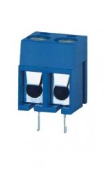
You mean these ? (below - euroblock terminal).
If you must use these .....
A 5mm lead spaced block terminal should fit between a smaller C13/C17 (12.5-15mm). Drill new holes for 12.5mm caps (below 2). Euroblock should fit.
A smaller C13/17 (220uf) should have little if any affect on performance.
Edit - I will incorperate this extra lead spacing into V2.4...
OS
Attachments
Last edited:
"boutique audio caps"
Is that what they call them !!
Link me to some .....
There is lots of "acreage" in the C4/C1 area . I could shift the input euroterminal
to the far right side horizontal. It would be under the cylinder of the "boutique" cap.
This would give about 40mm horizontal for C1.
OS
Is that what they call them !!
Link me to some .....
There is lots of "acreage" in the C4/C1 area . I could shift the input euroterminal
to the far right side horizontal. It would be under the cylinder of the "boutique"
cap.This would give about 40mm horizontal for C1.
OS
Is that what they call them !!
Link me to some .....
There is lots of "acreage" in the C4/C1 area . I could shift the input euroterminal
to the far right side horizontal. It would be under the cylinder of the "boutique"
This would give about 40mm horizontal for C1.
OS
Yes, I call them "boutique." On the other hand, some do not use the boutique word until the law of diminishing returns has been exceeded 4 fold and have spent at least 1K on them
... I will link to some "po-fella's boutique" caps tomorrow after work.Jason
Here are some quick ones
The polys-
The Madisound Speaker Store
The Madisound Speaker Store
The electrolytics-
UES1H221MHM Nichicon | Mouser
Okay, more tomorrow...
Jason
The polys-
The Madisound Speaker Store
The Madisound Speaker Store
The electrolytics-
UES1H221MHM Nichicon | Mouser
Okay, more tomorrow...
Jason
TMC ???
Search this thread .... http://www.diyaudio.com/forums/solid-state/171159-bob-cordells-power-amplifier-book.html
....for "TMC" - by post.
I had to weed through a lot of arguing and BS in the thread to come to the right choices for TMC. This is also why I left the option of standard miller comp. in the PCB.
(just omit R24 - jumper C8).
OS
By Janusz - It also would be nice to see in documentation explanation for some design choices, eg the chosen LTP and VAS vs dual symetrical LTP and VAS and possibly some discussion of TMC component values and implications of different choices as my practical knowledge of TMC is nonexistent and probably many other members are in the same boat as myself. Another example of component choices would be: using high Hfe Q1 and Q2 plus higher value degeneration resistors makes the amp a bit faster.
Search this thread .... http://www.diyaudio.com/forums/solid-state/171159-bob-cordells-power-amplifier-book.html
....for "TMC" - by post.
I had to weed through a lot of arguing and BS in the thread to come to the right choices for TMC. This is also why I left the option of standard miller comp. in the PCB.
(just omit R24 - jumper C8).
OS
Here are some quick ones
The polys-
The Madisound Speaker Store
The Madisound Speaker Store
The electrolytics-
UES1H221MHM Nichicon | Mouser
Okay, more tomorrow...
Jason
33-35mm (L) X 20-25mm (D) seems standard.
Done...
BTW - here are "boutique" caps for C5 and C9
.Nichicon Aluminum Organic Polymer Capacitors | Mouser
Datasheet :
http://www.mouser.com/ds/2/293/e-p_lv-257325.pdf
OS
You mean these ? (below - euroblock terminal).
If you must use these .....
A 5mm lead spaced block terminal should fit between a smaller C13/C17 (12.5-15mm). Drill new holes for 12.5mm caps (below 2). Euroblock should fit.
A smaller C13/17 (220uf) should have little if any affect on performance.
Edit - I will incorperate this extra lead spacing into V2.4...
OS
Yes, that's the one only I didn't know these are called euroblocks in the USA. It fits perfectly well into SPK-GND space so it will go there.
As I like having these caps in so on my v2.3 boards C13 goes under. In really fast amps these caps are needed to cater for these transient peaks. I remember that apart from these Otala liked 680nF fast poly cap plus 1ohm resistor (? if my memory is not failing) between each side of PS where it enters the board and dirty ground to compensate for big caps internal inductance etc.
cheers,
Hi OSC-Z = 12v-15v zener instead of R18.
C-R = 22K R18.
You could also use either component with either C-z or C-r.
Just make sure one of the jumpers are in place.
OS
I'm jumper C-R
I'm turn R30 about 10mV
R53 and R54 is burn,why
- Home
- Amplifiers
- Solid State
- diyAB Amp - The "Honey Badger"