The whole trick is to select diode and its location in such a way that under normal conditions it is reverse biased so it looks as if it was not in the circuit. However, when PA is driven into clipping diode should be forward biased so it would conduct to reduce the base current drive into VAS transistors.
On top of it depending on the amps design it may be essential that diode’s reverse leakage current is as low as possible. When building Stochino’s amp some crucial diodes had to be selected for that minimum reverse leakage currant.
So it looks that with some fine tuning of diode selection and placement Honey Badger will be as good as possible. Nevertheless, it is alvays better to operate LTP-VAS from regulated PS some +/-5V above below the output stage.
Cheers,
On top of it depending on the amps design it may be essential that diode’s reverse leakage current is as low as possible. When building Stochino’s amp some crucial diodes had to be selected for that minimum reverse leakage current.
This is hard , as some of the best ones are SMD.
Perhaps , on V2.4 , I should add pads for SMD and leaded devices (just for this part!!).
My results on some of the models I have not shared (yet) are near perfection.
But .... these are SMD (much greater selection).
OS
Last edited:
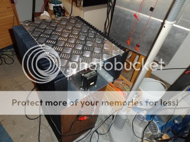
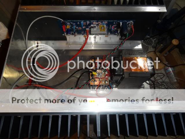
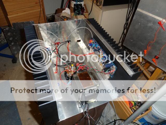
Well I got the case almost finished today. I didn't have a power jack so the AC portion is undone but i got everything else installed and tested. My goodness this is one beautiful sounding amp. Maybe my favorite so far. I hooked it up to my JBL's and it really kicks.
Sorry OS, I didn't get around to making any of the changes you suggested. The higher gain doesn't bother me because I am using a B1 Buffer for my preamp and it doesn't add any gain at all.
I played it through two pair of JBL for 4ohm and it just kicked without breaking a sweat. I just ganged 6, 10K 100W caps together for the PSU. Sounds really sweet and the bass if to die for. Tranny runs at 65.4V at an idle and drops to about 63.9V at high volume with deep bass parts playing. At normal listening, it runs right at 65V rails. I'm pretty happy, can you tell?
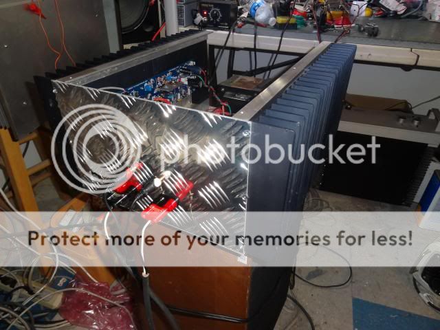
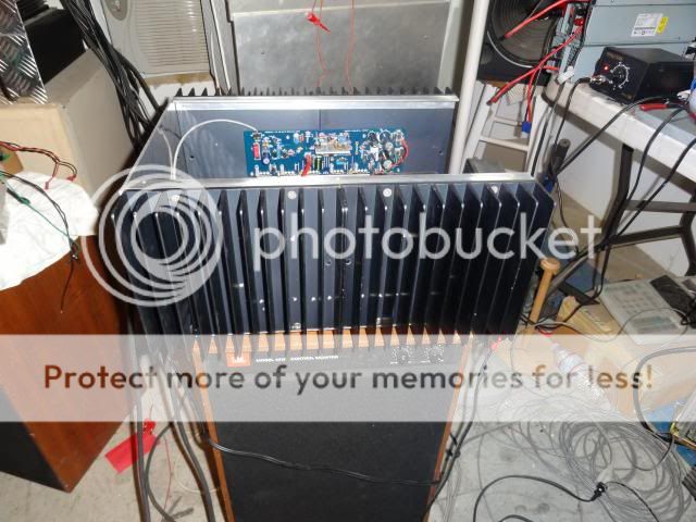
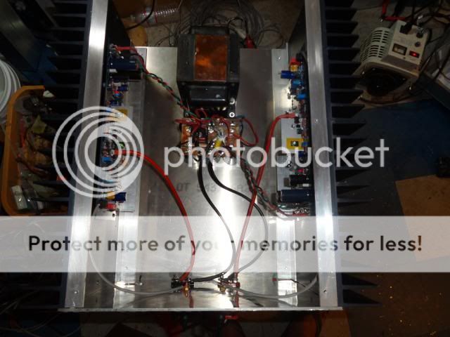
Here are some picks. I haven't done the face plate yet because it holds the power switch.
Sorry OS, I didn't get around to making any of the changes you suggested. The higher gain doesn't bother me because I am using a B1 Buffer for my preamp and it doesn't add any gain at all.
I played it through two pair of JBL for 4ohm and it just kicked without breaking a sweat. I just ganged 6, 10K 100W caps together for the PSU. Sounds really sweet and the bass if to die for. Tranny runs at 65.4V at an idle and drops to about 63.9V at high volume with deep bass parts playing. At normal listening, it runs right at 65V rails. I'm pretty happy, can you tell?
Here are some picks. I haven't done the face plate yet because it holds the power switch.


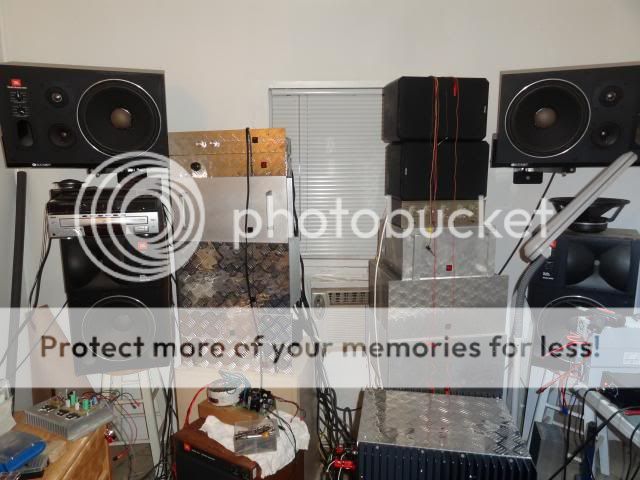
By still4given - I'm pretty happy, can you tell?
That case looks like it's built "ram tough" - truck style !
Wow ! that's a lot of amps, man....
BTW - if you do any change , replace the R24=1.5k (TMC feedback) , that
will get rid of the oscillations.
I love those classic JBL speakers , would not want to hurt them horns !!
OS
Last edited:
I used BAW62 diodes in the Stochino amp with absolutely no issues.
Badger's can see 120v reverse voltage in my diode application , BAW62 has only
PRV= 75V. I will look at NPX's BAWxx lineup for a 125-200PRV offering.
OS
Hello OS!
Would any of these do the trick? I see you used BAW21 which is among them. Which would be best, and what value for R18 and R24..
http://www.mouser.com/ds/2/302/BAV20-113648.pdf
http://www.mouser.com/ds/2/258/MMBD1501(A)-1505(A)(SOT-23)-25843.pdf
http://www.mouser.com/ds/2/149/FDLL485B-93325.pdf
Stian
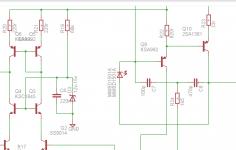
Maybe a few more words on the diode selection and its placement. I made a suggestion to connect base of Q9 to the collector of Q10 but then I went to that page Ostripper recommended in another thread. There were no schematics so I thought that they are talking about some general rule so I hesitated. That's why I posted the other note that it would have worked for the upsidedown LTP-VAS and it would have as with such configuration collector of the lower VAS transistor has to be connected to something with higher potential than its base to "pull it up" from the rail when overdriven as it cannot go below rails voltage and gets saturated.
If the main VAS transistor is on the positive side then the collector of the upper VAS transistor has to be connected to some point with lower potential than its base so under normal conditions the diode is reverse biased. When overdriven, however, diode becomes forward biased and "pulls down" the collector of the upper VAS transitor from its rails voltage to prevent transistor's saturation. In this case collector of Q10 can be connected to the base of Q9 or its collector as these have lower potential than its base.
Conclusions for the dode selection as already mentioned before by ostripper are:
1. It must have reverse breakdown voltage high enough to sustain the whole swing (-V to +V);
2. it should have low reverse leakage current not to degrade amp's performance when it is reverse biased under normal operating conditions.
cheers,
Hello OS!
Would any of these do the trick? I see you used BAW21 which is among them. Which would be best, and what value for R18 and R24..
http://www.mouser.com/ds/2/302/BAV20-113648.pdf
http://www.mouser.com/ds/2/258/MMBD1501(A)-1505(A)(SOT-23)-25843.pdf
http://www.mouser.com/ds/2/149/FDLL485B-93325.pdf
Stian
All those look real good (<50nA leakage/>150V prv). The last 2 SMD devices could be soldered right across the Q9-B/Q10-C pads under the board , no rework.
R18/19 are the cascode divider resistors. R18 can be replaced by a 7-24V (12/15V optimal) zener. 68K for R19 will be >500uA (1/2mA) with >50V rails. 40-50V rails can use 56K to keep 1/2mA current.
If using resistors , just try to keep 1/2mA flowing through R18/19. This will
be 68K/22K (60V rails) or 56K/15K (40V rails).
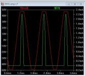
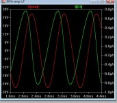
(Below-attachment 1) is a overdriven badger with a murs120 clamping diode.
Notice the (green) pulse of the diode clamping the Q10 transistor at clip. 2-3mA is all that's required (any small signal high-speed diode).
(below-attachment 2) is the badger under normal conditions. The green is the reverse leakage (500nA). This is worst case ... as some of the better SMD diodes have 1/10th the leakage.
For those PURISTS !! Do not add the diode , R24=1.5k (TMC feedback) , DO NOT CLIP - you won't have the "little burst" , but you will "stick" (Q10) , if
you do.
OS
Attachments
Sounds great OS.
Take a look at my attachment, does it look somewhat correct? What value would you recommend for R19 at 80v?
I used this amp almost for a month earlier, and is now waiting for me to complete the cabinet for it. Ive fitted the honey badger with 4 pairs of outputs instead of 3. It seems to work pretty good, except i get some banging in my speaker when i reach high sound levels with much peaks of bass, and after i saw the posts these latest days, i though maybe that could be the cause for the bangs. Other than this, honey badger rocks with 4 outputs.
Attachments
I wouldn't worry about asymmetrical clipping causing DC offset; at the levels where this happens, the dissipation in the voicecoil caused by pk-pk voltage is many times larger than that that would be caused by the DC offset AFAIK. My diode method can actually increase output swing, if the current drawn through the diode isn't too large.
As far as the TMC, If it rings after clipping, there is a good bet that the compensation is undersized anyway and that response is peaking at high output voltages and/or high currents.
As far as the TMC, If it rings after clipping, there is a good bet that the compensation is undersized anyway and that response is peaking at high output voltages and/or high currents.
Sounds great OS.
Take a look at my attachment, does it look somewhat correct? What value would you recommend for R19 at 80v?
I used this amp almost for a month earlier, and is now waiting for me to complete the cabinet for it. Ive fitted the honey badger with 4 pairs of outputs instead of 3. It seems to work pretty good, except i get some banging in my speaker when i reach high sound levels with much peaks of bass, and after i saw the posts these latest days, i though maybe that could be the cause for the bangs. Other than this, honey badger rocks with 4 outputs.
Your "banging" could be you bottoming out the voice coils. 4 outputs at 80V !
= 300+ w peaks (at least).Your schema(s) are ideal , R19=68K at 70-80V would be 600uA through the
zener.
Your clamp diode and R24=1K5 are also ideal.
Could you share your model for that diode ?
Attach a text file or just paste it...
OS
A useful clipper, probably good for woofer amp.
Banging the voice coils. . .
I think it would work to replace the feedback-shunt resistor (not the feedback resistor) with a similar value of multi-turn potentiometer, add antiparallel diode to the wiper, add add a series resistor (about 390R-ish) between the diodes and the IN+.
There's your standard LTP Clipper except that I've added a base stopper resistor (just a bit of padding between those diodes and the in+) so it won't make a strong change to your compensations/tone. You could add a cap series with the diodes for decreasing the brightness of switch-on tones.
Anyway, turn the dial till the speakers don't bang.
This approach might be useless with Honey Badger; however, I think that a dial like that (or with similar function) would be really valuable for Bass Badger (align the amplifier to match the woofer capacity).
Last edited:
It might help to put antiparallel BAT86 across the LTP bases. The diodes will turn on and prevent the LTP from saturating, which may improve recovery and sticking.
Dan's idea is a hybrid solution which combines this with a variable threshold and variable soft voltage limit. All these effects sort of run together, for better or worse depending on what diodes you choose, what input and feedback resistors, and your degeneration voltage. It's fun to figure all that out.
Dan's idea is a hybrid solution which combines this with a variable threshold and variable soft voltage limit. All these effects sort of run together, for better or worse depending on what diodes you choose, what input and feedback resistors, and your degeneration voltage. It's fun to figure all that out.
It could be the voice coils bottoming, but it really does not sound like that.. Sounds more like an electrical error and not mechanical.. If its still the same when i get together the case and attached the diode, ill hook up the scope to output when it happends.
Model for this diode can be found here, atleast this is the model i could find for it(fairchilds edition):
mmbd1501a - Datasheet Archive / mmbd1501a - Datasheet Archive
Model for this diode can be found here, atleast this is the model i could find for it(fairchilds edition):
mmbd1501a - Datasheet Archive / mmbd1501a - Datasheet Archive
Banging the voice coils. . .
I think it would work to replace the feedback-shunt resistor (not the feedback resistor) with a similar value of multi-turn potentiometer, add antiparallel diode to the wiper, add add a series resistor (about 390R-ish) between the diodes and the IN+.
There's your standard LTP Clipper except that I've added a base stopper resistor (just a bit of padding between those diodes and the in+) so it won't make a strong change to your compensations/tone. You could add a cap series with the diodes for decreasing the brightness of switch-on tones.
Anyway, turn the dial till the speakers don't bang.
This approach might be useless with Honey Badger; however, I think that a dial like that (or with similar function) would be really valuable for Bass Badger (align the amplifier to match the woofer capacity).
Show an example. I'll run it through the LT grinder.
OS
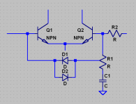
Here's the basic thing. Values aren't shown because it's not one-size-fits-all. I suggest using low-capacitance schottkeys. Some diodes actually have too low voltage drop and leakage is too large in this position, I think the 1N5817 is an example (but I think that has too much capacitance anyways).
Attachments
- Home
- Amplifiers
- Solid State
- diyAB Amp - The "Honey Badger"