I agree. The cost of an 800VA over a 600VA is minimal, so I may consider upgrading. I was already planning to include a softstart switch. Just waiting for the PCBs to arrive and the components from Mouser.The correct size transformer for a two channel 150W amplifier would be 300VA-600VA. If to be used for 4ohm speakers, 600VA would be the minimum. Since the difference in cost is negligible, at least here in the states, it would be worth bumping this up to 800VA. 1000VA is overkill. If a toroidal transformer is used, a softstart circuit will be mandatory.
42VAC-45VAC is correct.

If anyone is in contact with OSTripper can you please get him to contact me via PM or email (he also has my email address). I have been trying for a long time with no success. Thanks!
He's a sly one. Likes to disappear from time to time. Wonder if he's still reading these posts??
I'm comtemplating a pair of HB monblocks to drive a set of Magneplanar SMGa. I'm also looking at class d/t.
Has anyone tried using a smps ? Something like this Connexelectronic in place of 2 x300VA transformers and a brace of psu caps.
Has anyone tried using a smps ? Something like this Connexelectronic in place of 2 x300VA transformers and a brace of psu caps.
You can't go wrong with an SMPS PSU from Connexelectronic (Cristi V.). I won't use one for my next build (HB), but I have used several of Cristi's SMPS' and they are quality built units. A little on the higher $ side, but you get what you pay for. I'm presently using the older brother of the 300RE, the 500R. It's rock solid and sounds great with my little class D amp. I do have the 300RE it's just not in service yet. Plan on using it for another lower-powered, IRS2092 based build from Cristi too.I'm comtemplating a pair of HB monblocks to drive a set of Magneplanar SMGa. I'm also looking at class d/t.
Has anyone tried using a smps ? Something like this Connexelectronic in place of 2 x300VA transformers and a brace of psu caps.
Rick
I'm comtemplating a pair of HB monblocks to drive a set of Magneplanar SMGa. I'm also looking at class d/t.
Has anyone tried using a smps ? Something like this Connexelectronic in place of 2 x300VA transformers and a brace of psu caps.
I'm testing a Connexelectronic SMPS800RE (+/- 60V) PSU with the honey badger. There is a tiny bit of noise evident on sensitive speakers for a few seconds after playing loudly and then cutting the sound. I'm making the assumption that its line noise rather than radiated noise at this point, but I haven't measured to confirm that. I may also add that I've deliberately gone for a larger supply as I'm planning to run 3 channels in a single enclosure and experiment with driving a 3 way active speaker using the three channels. Once I get three driven simultaneously I'll do some more testing as the PSU will have a higher base load.
I'd love to do a side by side test using a linear PSU, but I don't plan to spend that much, and I'm not sure it would be easy to find the space in the enclosure I've chosen. It would be easy with a 2 channel setup, but I want to fit 3 channels and a miniDSP just to complicate things.
The Connexelectronics PSU does seem a good unit, but I may need to investigate filtering if I still get audible levels of noise. Plan B is back to a linear PSU. That said, I'm already well down on the audible noise levels from the previous class T amplifiers I was playing with.
SMPS800RE looks like a typical car stereo dc/dc switch mode converter. It is more similar to your typical PC power supply in that it switches 160Vdc rectified wall AC into the final DC. Try ferrite chokes at the output rails. On the PC supplies there are the to-220 rectifiers , then the chokes , finally - the capacitors.
Really , a linear supply is recommended, but a SMPS could be optimized with proper design
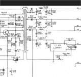
. Connexelectronics modules might not be (fully - {diplomatic} ) optimized for audio. (I said it) , the lack of those ferrites leads me to believe so. Edit - Almost all the google examples of SMPS show CLC output filters (example below)
OS
Attachments
Last edited:
The bigger problem might be ground noise rather than rail noise. To fix that you would need chokes on every output of the SMPS.
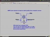
I made a simple device to fix ground noise issues on my bench. It isolates source and amp ground and removes the ground noise from the signal. The result was a big improvement in sound. I measured 25mV of SMPS nastiness between the two grounds (the source is my computer). Even 5mV of ultrasonic noise can affect an amplifier negatively, especially highly compensated amps.
I made a simple device to fix ground noise issues on my bench. It isolates source and amp ground and removes the ground noise from the signal. The result was a big improvement in sound. I measured 25mV of SMPS nastiness between the two grounds (the source is my computer). Even 5mV of ultrasonic noise can affect an amplifier negatively, especially highly compensated amps.
The bigger problem might be ground noise rather than rail noise. To fix that you would need chokes on every output of the SMPS.
I made a simple device to fix ground noise issues on my bench. It isolates source and amp ground and removes the ground noise from the signal. The result was a big improvement in sound. I measured 25mV of SMPS nastiness between the two grounds (the source is my computer). Even 5mV of ultrasonic noise can affect an amplifier negatively, especially highly compensated amps.
Hello , keen. Since many of us use a sound card as a source , please share. I use line filters on my amp and derive my amp's ground from the same AC strip as the PC. This has minimized "nastiness" ... but not eliminated it.
Ultimately , a DAC/optical spdif to the amps would be ideal - but not everyone wants to go that far !
OS
This was my first project. Super easy DAC kit that uses a wall wart. Sounds fantastic, markedly better than my M-Audio soundcard.
The γ1 Modular Miniature DAC
The γ1 Modular Miniature DAC
This was my first project. Super easy DAC kit that uses a wall wart. Sounds fantastic, markedly better than my M-Audio soundcard.
The γ1 Modular Miniature DAC
Cool
, I would keep my sound card ... just use it's SPDIF for my 2 full range Badgers and the dirty ol' sub output for my "bassbadger".Here's one:
Great Hifidiy USB Valve Tube DAC Kit Free Shipping | eBay
Has a tube !!
Or ....
Hifimediy Sabre Coax Optical DAC ES9023 CS8416 115V incl PSU Ships from USA | eBay
Prebuilt - would have to do more research first .
OS
I must warn you, it's very sacrilegious. I didn't want to myself, but my curiosity got the best of me and it was so easy, I couldn't resist. Especially after getting a new pack of alligator clips.
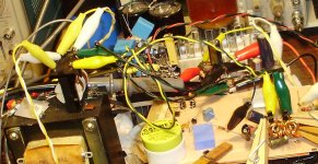
I used a CM choke from a computer PSU. I chose based on how it sounded used as a coupling transformer. This one had the best treble and imaging, as much as I could tell without the bass that is (. It is split bobbin with thick wire so the windings are nearly identical. The better matched the windings are, the more ground noise cancellation you will get. Still, 10% matching gets you 1/10 the original ground noise, which is not true for the groundlift resistor.
Coupling trafos are often suggested for ground noise problems but they have a bad reputation because of distortion. I had the idea of turning the trafo 90 degrees.
Ground noise has many different forms it takes. The electromagnetic form depends on current. As long as current is allowed to flow through the ground connection, there will be EM radiation, and there will also be effects depending on the grounding schemes of the source and amp. If your amp is isolated from ground, you'll still have several nF's leakage through the trafo and this will resonate with the total ground loop inductance, which may actually be worse. Furthermore, as long as any current flows through ground, there will be a corresponding ground noise between source and amp. Evidently isolating ground is not a bad idea. While interconnect ground resistance may be very low, inductance will dominate anyways, so actual ground coupling at frequencies that matter may not be effective.
A ground lift resistor is commonly employed to prevent excessive ground loop currents. The problem is that any voltage difference across this resistor is added to the input signal. So you are just trading one kind of noise for another. Both options don't sound good if you have a ground noise problem.
Using the trafo/choke in this way eliminates trafo distortion because the signal and return field cancel without any action caused on the part of the choke/transformer. I have measured the distortion of my EC buffer through this thing and it must have been well below .001% levels. It is difficult to make a transistor circuit that works this well. But what was really convincing was the increase in soundstage depth and realism. Ground noise is directly subtracted from the input signal.
You can try any trafo/choke with this as long a the winding ratio is 1:1. The choke I used is probably not far from 30mH; it won't block ground faults at 60Hz but even so it improves the sound a lot. Things to try would be:
1: Bifilar wound vs split-bobbin choke/trafos (cancellation vs leakage)
2: Toroidal cores (the choke can pick up interference as well)
3: Audio coupling transformers (with series resistor for the ground winding to prevent destruction on faults).
4: Isolation transformers, since they are sure to get down to 60Hz.
One interesting thing about this circuit is that it doesn't necessarily replace the groundlift resistor. The trafo does its job regardless of the groundlift resistor. If your amp is isolated, you want to pick a value for this resistor that adequately damps ground leakage resonance. For me this was 1k. You could make this a trimmer. Still, we want ground current as low as possible for reasons I've given above and I've found that a larger resistor sounds better as long as it's not too high. But if your amp is not isolated (mine was), you don't really need the resistor.
I just realized, the CM choke is sitting on top of a huge trafo that might work better... Right under my nose.
BTW OS, Jason was looking for you. It seemed important.
Attachments
This was my first project. Super easy DAC kit that uses a wall wart. Sounds fantastic, markedly better than my M-Audio soundcard.
The γ1 Modular Miniature DAC
Which M-audio card? To my ears the FW410 is pretty darned good. YMMV, of course.
BTW OS, Jason was looking for you. It seemed important.
They found me...
I like your style , Keen (the E-waste solution).
So , a 1:1 PC line filter inductor (cm choke?) will work , I have 2 of them (PC SMPS's are everywhere).
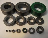
I also have some of these (below - lots of them) and some enameled wire. Could I use these ?
Do the direction of the windings have any importance ?
If I wound my own I could get perfect 1:1.
The PC SMPS ....
250 W S.M.P.S. with Power-FETs James Arthur
typically has 25K- 40K "nastyness".
The CM (common mode) choke ...
Basics of Noise Countermeasures [Lesson 6] Common mode choke coils | EMICON-FUN! | Products | Murata Manufacturing Co., Ltd.
(that link answers my winding question -figure 3)
... not only blocks line noise coming in , but SMPS noise going out (back to the AC line). My concern is how this might effect the audio. I would guess the ferrite chokes are wound to block 25K+ (the PC's SMPS freq.) and any higher order harmonics additionally generated.
BTW , the ground noise I actually saw when I had my scope was indeed HF (sawtooth waveform- 20k+ from the PC).
OS
Attachments
Last edited:
If you get the winding wrong, you may hear a very high-pitched buzz. I turned the clips around and it was gone. If you're winding bifilar with double wire, then your source will be on one end of the wire pair and the amp on the other. The magnetic field of the input current cancels out the field of the return current of the same.
For a 30mH CM choke, rejection extends down to 1KHz or so. You can test this in LTSpice with a simple model. 30mH is around the values for CM chokes that I've looked at.
For a 30mH CM choke, rejection extends down to 1KHz or so. You can test this in LTSpice with a simple model. 30mH is around the values for CM chokes that I've looked at.
SMPS800RE looks like a typical car stereo dc/dc switch mode converter. It is more similar to your typical PC power supply in that it switches 160Vdc rectified wall AC into the final DC. Try ferrite chokes at the output rails. On the PC supplies there are the to-220 rectifiers , then the chokes , finally - the capacitors.
Really , a linear supply is recommended, but a SMPS could be optimized with proper design
Edit - Almost all the google examples of SMPS show CLC output filters (example below)
OS
That was my fear, but I thought I'd give a SMPS a try. My issue is that I want to fit 3 honey badgers and a miniDSP into a case to have a full set of drivers for an active speaker system and using a linear power supply would use a lot of the available space. I also need to manage any EMI issues if I stick with a SMPS.
My current plan is for a SMPS, 2 HBs on the enclosure's sidewall Heat Sinks, and a 3rd HB on a seperate HS mounted inside the enclosure. That internal HS take a lot of space where the transformer would normally be mounted. I was hoping a SMPS would allow me to significantly reduce the required real estate, and at least one has received good reviews in The Wire thread. But I guess everything comes with tradeoffs, and a low-cost SMPS like that from Connexelectronics has its share.
A second option is to move a pair of HB boards onto a single HS (380x140x32), but I have no idea of the thermal properties of the heatsink. If I decide to 'downrate' the amp specs to say 100-150W per channel both the power dissipation and transformer/PSU rating issues become less of an issue.
Part of the fun of DIY is the learning experience. Once I sort the best option I'll be building 3 amps, with a total of 9 HB boards! Nothing like overkill to keep you happy. Yes, I know the HB is significant overkill for driving a tweeter, but I wanted to keep the option to later remove the miniDSP and convert the amps back to a more normal three channel power amplifier.
I'll have a play with CLC filters, and also see if I can't acquire a transformer from somewhere at minimal price and compare results.
If you get the winding wrong, you may hear a very high-pitched buzz. I turned the clips around and it was gone. If you're winding bifilar with double wire, then your source will be on one end of the wire pair and the amp on the other. The magnetic field of the input current cancels out the field of the return current of the same.
For a 30mH CM choke, rejection extends down to 1KHz or so. You can test this in LTSpice with a simple model. 30mH is around the values for CM chokes that I've looked at.
30mH would be 200 windings + x 2 for common mode on my 20mm toroids .
I used a online calculator ...
Online Calculator .:. Amidon Toroid Calculator (Ferrite)
Better to salvage some pre - made ones from E-waste.
OS
Which M-audio card? To my ears the FW410 is pretty darned good. YMMV, of course.
I have the Delta Audiophile 192. It does OK but the DAC really opens up with clarity and definition in the high end. Stereo separation seems better too.
- Home
- Amplifiers
- Solid State
- diyAB Amp - The "Honey Badger"