Yup , just lose a volt before clipping.
No issue with performance. This is the best VFA I have simulated.
No issue with 6ppm at one pair outputs/8R.
(and 6ppm / 3 pair / 2R !!)
OS
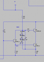
-R18 is dissipating .25W, we can cut that in half if we change it to 27k and tie it to ground instead of the positive rail.
-Add a .1uF bypass cap across the LEDS D1-D3, this will lower distortion just before the onset of clipping at 20kHz from ~150ppm to ~50ppm.
-Maybe add a 2.2-10ohm base resistor on Q12 in case of parasitic oscillation.
Attachments
HBV2
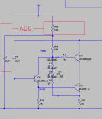
Finally caught up on the thread. It could not have come at a better time as with the travel restriction over the Christmas break, I had been looking at modifying the Honeybadger and came up with the following circuit. I was starting to simulate it in LTSPICE when I discovered the update to this thread. Extremely useful information on the decisions and explanations of the V2 development Ostripper and Keantoken") thanks. Looking forward to the development of HB version 2!
thanks. Looking forward to the development of HB version 2!
Finally caught up on the thread. It could not have come at a better time as with the travel restriction over the Christmas break, I had been looking at modifying the Honeybadger and came up with the following circuit. I was starting to simulate it in LTSPICE when I discovered the update to this thread. Extremely useful information on the decisions and explanations of the V2 development Ostripper and Keantoken
thanks. Looking forward to the development of HB version 2!Attachments
Finally caught up on the thread. It could not have come at a better time as with the travel restriction over the Christmas break, I had been looking at modifying the Honeybadger and came up with the following circuit. I was starting to simulate it in LTSPICE when I discovered the update to this thread. Extremely useful information on the decisions and explanations of the V2 development Ostripper and Keantoken
I saw it , there are many things wrong with that schema. It would work ,
but no 5ppm with that.
PS - looks like nakamichi OPS.
OS
-R18 is dissipating .25W, we can cut that in half if we change it to 27k and tie it to ground instead of the positive rail.
-Add a .1uF bypass cap across the LEDS D1-D3, this will lower distortion just before the onset of clipping at 20kHz from ~150ppm to ~50ppm.
-Maybe add a 2.2-10ohm base resistor on Q12 in case of parasitic oscillation.
1. Ground reference decreases 500hz and down PSRR by 15db+.
2.I like this one , it increases local FB to the cascode.
3.I also like this one , good call.
I mentioned you in the Slewmaster thread as the "unknown member"
.OS
under normal music listening, probably nothing....
but try to short the output of the amp for a couple of seconds with music signal present, see how things change so fast.....
some designs i think has mitigating measures built in, Leach did it with his amps....for that eventuality that no one wants and much less anticipated...
this is the reason we had the honey badger redesigned for on board SOA protection...
there are even plans to convert this design to class H...
This should be done with active current/DC monitoring. Output clamps
are so 20th century. Slewmaster tech , we are beyond this old school.
21st century (Vaudio tech) , they have this in hand. Output emitter resistors
are monitored in real time .... PIC u Processor trips the SS relay. Done !!
Class H, I played with this in my greenamp adventure. DIYA fundamentalists
would never convert !!
V2 , If Jason goes for it .... will have EVERY protection onboard.
I would NOT bother to be here (after 5 years) to redesign it if this was not true.
NO more DIY level stuff - commercial/industrial level audiophile designs
are my forte.
OS
Last edited:
A mosfet ,
OS
well, Nelson Pass liked them mosfets a lot...
Last edited:
1. Ground reference decreases 500hz and down PSRR by 15db+.
2.I like this one , it increases local FB to the cascode.
3.I also like this one , good call.
I mentioned you in the Slewmaster thread as the "unknown member"
OS
1. Bummer... as far as decreasing PSRR. I'm fine with tying R18 to the positive rail but if you still want to entertain lowering the dissipation, what about doing this to keep R18 current constant? Also what is your method of measuring PSRR in LTspice?
HaHa I've read a lot on diyAudio but I've never posted before.
Attachments
Opinions on this chassis being sutible for Honey Badger? It's an old Ross Systems MegaAmp 400, there are four heatsinks, two each side and measure singularly L140mm, H90mm and W40mm. If I went with this due to the pcb footprint I would have to use an 'L' shaped bracket to mount the outputs then mount this to the heatsinks.
Found this forum about 6 months ago looking for a DIY class a/b amp that I could build (last one I built was a SLO 100 Tube amp) some reason could not find any decent Gerber files let alone good information on a good measuring diy amp. Got the email saying boards n stock so got my order placed but want to get more made from some place. I wish any future builders the best of luck! has anyone had this amp professionaly measured/ tested? Thanks again cheers!
Okay, I got everything biased up per the guide on one channel. I hooked up the input and out, spun up some music and...... nothing lol. That's a first for me. I think it's something on the input side, this build has been a pain in my rear.
I'm not sure if I want to troubleshoot it, or just move on.
I'm not sure if I want to troubleshoot it, or just move on.
I didn't think that was needed if you had a large C1 that was wider that the first two holes...
EDIT:
I did some quick testing and I should show short from on side of C1 to R2 and read R2 on the far side of R2. I do not. I show an open on both sides, so yes, I think you are right. The problem is it's a huge C1 and will require me to dismount the entire board from the heatsink to allow me to get to it to solder. ()@&*&_*$_@#Y
Last edited:
Yup I see it now and the tests confirm it.
I managed to sneak a jumper in without taking the whole thing off the sink. After I soldered it in the values showed correct. I fired it up and she is working on one side. I have a few parts on the way for the other channel. I'll be glad when this one is done.
A big thanks for the heads-up AS.
JT
I managed to sneak a jumper in without taking the whole thing off the sink. After I soldered it in the values showed correct. I fired it up and she is working on one side. I have a few parts on the way for the other channel. I'll be glad when this one is done.
A big thanks for the heads-up AS.
JT
- Home
- Amplifiers
- Solid State
- diyAB Amp - The "Honey Badger"