Yes, I see that, but I don't think we want to short that. As I'm sure you know it will remove the local feedback in the VAS and it will be less linear due to the increase in re'R23 is the VAS emitter resistor, are we talking about the same thing?
I was just saying that just try running one output pair and see the difference. I am also taking my output prior to the zobel network.
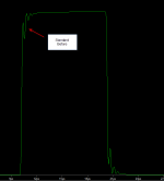
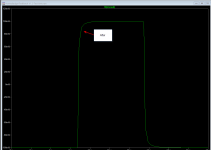
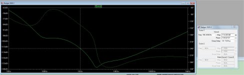
The results are posted below - .0029% at 20khz , and 75-80degree phase margin
at unity gain.
What is cool is that this amp is quite similar to the uPC1342 - "Badger on a chip".
My simulation seems to reflect the Sony uPC amp perfectly - the sony
rates as 800k UG/with .01%THD 20k ... Badger has more outputs , less THD.
The Sony also just uses CMC (68pF).
OS
From my calculations and actual testing the stock HB has a UGCF of around 710Khz
If you use a 68pf cap fir C7 only you end up with a UGCF of 860Khz
With larger resistor through holes please
A lot can be learned in 9 years.
Attached is an updated Badger with 2016 Keentoken and Cordell models.
Put the KT-Cordell models.txt in the same folder as the DIYA-amp-LT.asc.
This is the 2012 original simulation of the Badger (with my changes).
I noticed with the new more accurate models that the badger was a (near)
oscillator.
From the Slewmaster and my EF3 "adventures" , I removed the driver
basestoppers (R34/35). I also reduced the VAS gain (note R22/R23) and
used a 68pF conventional miller comp.(C8 ...eliminated C7).
The results are posted below - .0029% at 20khz , and 75-80degree phase margin
at unity gain.
What is cool is that this amp is quite similar to the uPC1342 - "Badger on a chip".
My simulation seems to reflect the Sony uPC amp perfectly - the sony
rates as 800k UG/with .01%THD 20k ... Badger has more outputs , less THD.
The Sony also just uses CMC (68pF).
OS
Last edited:
You want to clip somewhere the energy won't be stored and come out later in sticking, latching or spiking. It's not always the same, even for similar looking schematics or even the same amp with different component values.
Or maybe some sticking is acceptable if it allows for better performance in reasonable listening conditions.
It all depends on what is on the bench, and the purposes you have for it...
clipping is always bad news and is best to avoid......so knowing the limits of your amp and staying below limits is always good...
Hi OS, Thank you for sharing that circuit in post 2224. I tested the circuit that you attached with a 100Khz pulse and removing C2 and I still see the same behavior.
In fact it appears to be worse that what I was seeing in the simulation that I was running on the original schematic. What are your thoughts OS?
When I remove the Output stage completely and connect the NFB to the drivers the output is perfect.
This may fix it.
I'll also list them order of contributions to the oscillation.
Change R36 to 50R (1)
Change R34/R35 to 2.2R (2)
Change C18/19 to 100pf (3)
Change C20 to 10nf (4)
Before and after results shown in images
Attachments
Last edited:
Sooooo many amps , so little time. DiYA can have this one on the house.
Just want to see happy woofers and tweeters.
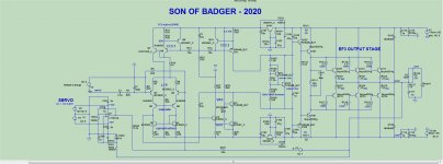
Well , here it is (below).
1. Cascoded BC560 beta enhanced VAS with matching Toshiba 5W devices.
Runs at 4ma - most likely won't need that stupid VAS heatsink.
2. "Slewmaster" EF3 - Don't need to prototype these -
many, many, slewmaster's attest to that. With 3 pair outputs ,the oversized drivers
might also need no heatsink (unless with 3 pair MT-200 sankens and
brutal 2R subwoofer duty). A small heatsink with all other uses. The slewmaster
also has a second Vbe on the drivers . The Harmon- Kardon amp that inspired
this OPS uses a small to-126 on the driver pair HS to quickly respond to
thermal changes. The original HK amp just sandwiched this second Vbe
between 2 raw drivers.
3.Same CCS's as the original badger. Classic "blameless".
4.Ah , cap multipliers. This Badger walks on water in the PSSR department.
5. Servo - Heck with offset trimmers and closely matched LTP's .
Still working on it. VERY nice to have a 16 core PC to use LT on - wow!!
(Intel Xeon V3 DDR4 system - 32Gb ram),
ALL ideas are most welcome !
OS

The schematic looks kind of familiar! I can help with the layout whenever you're ready if you like.
hey OS, any reason for dumping the ltp cascode in your new scheme?
To keep the parts count down.
What we lose with the ltp cascode we gain back
X2 from the VAS cascode and the EF3.
We also added the Servo.
Edit - zener free design.
os
Last edited:
The schematic looks kind of familiar! I can help with the layout whenever you're ready if you like.
Yes , It is a modified (wolverine). And YES , you are the master of protection.
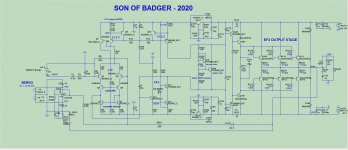
This (below) is very cool - the IPS uses just 11ma per rail. Could we mix a little
SMT into it ??
The sim (attached) just wants to work. I can push UG up to 3mhz , no issue.
Still might need the Baker clamp option on the VAS. 2R loads on this sim better than 8R on the Badger.
PS - This amp is a "SOB" (bastard son of wolverine+badger).
OS
Attachments
Hello Ostripper
greetings nice to see you back is schematic in post #2227
ok to build .
warm regards
Andrew
Nope, #2252 is (golden).
The sim is continuing to impress me. Continuing to fine tune the square wave and bandwidth of this version. Very promising.
OS
PSRR rrrrrg !
1.Added C5/6 to the input stage - It is just a discrete op-amp .. OK !!
2.Added C107/108 to the EF3 decoupling. I saw a "glitch" at 5mhz. Dumb me,
the Slewmaster EF had those caps. rock solid.
Amp now has -100db from 100hz to 200khz PSRR.
Most of the audio range from 500hz to 20khz is rock bottom -120db. Cool !
3. C4 -47pF + R3/4 -47R are best (absolute) non-ringing vs. best bandwidth
(1.3mhz) combination. C4 @ 68pF is 1mhz UG (very safe) - still 5ppm at 20Khz
THD. Nice.
PS - any ideas on how the implement the baker clamp option on a cascoded
beta enhanced VAS ???
OS
Attachments
SMT would make it a lot easier to source parts, but I'm not sure how many would want to build it. Making it available with a solder stencil would make it a breeze to build though.
2n5401 is now a big buck transistor. BC550/560 are going the way of the Dodo too. Pickings are getting slimmer every day for small signal through hole devices.
2n5401 is now a big buck transistor. BC550/560 are going the way of the Dodo too. Pickings are getting slimmer every day for small signal through hole devices.
This is fact ! I have been looking at many of the low voltage SMT's. That is why
just the cascode and VAS are high voltage.
I don't know , a year or two from now ... DIYA could be in the realm of the
luddite. Booo hooo.
I am tailering the design with the SMT option in mind. I don't know why they resist ??? No holes , no clipping leads ?? Much shorter traces are a plus.
PS - perhaps a VZaudio type SMT IPS/VAS (daughter card) plus through - hole for the big stuff.
OS
Last edited:
I do my commercial stuff with SMD and just done a DIY phono pre (audioXpress) that's all SMD. Its the way to go and I would encourage everyone to take the plunge. I think in 5 yrs you wont be able to get through hole SS transistors. NXP stopped making BC5XX in 2006 - went completely to BC8XX.
(Nice design by the way Pete )
(Nice design by the way Pete
)I like the separate input board design. Much easier for testing. No worries of blowing output devices that way. This is all something that should be bounced off Jason though, as he'll be the one selling them. Maybe he should start a poll to see what builders would like to see?
- Home
- Amplifiers
- Solid State
- diyAB Amp - The "Honey Badger"