I want to build a simple amp for an active Subwoofer and I try to use the IRFp4668 for it.
The circuit is based on the Elektor amplifier called Buzamp. It was not easy to find a stable setting with LTspice and I hope the circuit works.
Unfortunately I have no matching transformer at the power limit of the MOSFET. The only thing available is a 500VA toroid with 2 x 30V.
The first idea:
There is the question of how much heat can dissipate the Mosfets.
The circuit is based on the Elektor amplifier called Buzamp. It was not easy to find a stable setting with LTspice and I hope the circuit works.
Unfortunately I have no matching transformer at the power limit of the MOSFET. The only thing available is a 500VA toroid with 2 x 30V.
The first idea:
An externally hosted image should be here but it was not working when we last tested it.
There is the question of how much heat can dissipate the Mosfets.
Last edited:
You are going to have a hard time with this circuit, because the transistors Q6, Q7 and M3 and M6 do not "track". The power rating and derating of the MOSFET should be in the data sheet.
It would work if you used lateral mosfets, with vertical ones you need a VBE multiplier mounted on the heatsink to keep thermal stability in check.
Yes, Q10 is provided for the thermal coupling.
@sawreyrw: What do you mean with track? The IRFP4668 have a max. power dissipation of 520W. But can the chip size dissipate the heat?
@sawreyrw: What do you mean with track? The IRFP4668 have a max. power dissipation of 520W. But can the chip size dissipate the heat?
Yes that device is rated at 530W BUT that is if you keep the case at 25C or less.
But to keep the case at 25c or below is damn near inpossable you would need to mount it on a flat heatsink with thermal compound and no insulator and have the
area under the device at about 100C below zero and anyway that device will be hard to drive with a ciss of 10,720 pf.
But to keep the case at 25c or below is damn near inpossable you would need to mount it on a flat heatsink with thermal compound and no insulator and have the
area under the device at about 100C below zero and anyway that device will be hard to drive with a ciss of 10,720 pf.
Hi,
Seems bridging (BTL) would use that transformer more effectively.
Sub amps just have to be effective, not flash, bandwidth is so low.
rgds, sreten.
Seems bridging (BTL) would use that transformer more effectively.
Sub amps just have to be effective, not flash, bandwidth is so low.
rgds, sreten.
Last edited:
I have changed the circuit a bit. The small driver for the Mosfets works in the simulation very well.
I think, it's time for a prototype.
I think, it's time for a prototype.
An externally hosted image should be here but it was not working when we last tested it.
Here some simulations:
Bandwidth with compensation:
Bandwidth without compensation:
open loop gain:
FFT 50Hz 1Watt:
THD: 0.011%
Square 100Hz:
The amp is stable up to 100 nF in parallel to the exit. I am thinking of a coil in the output to ...
Let's see what the reality shows.
Bandwidth with compensation:
An externally hosted image should be here but it was not working when we last tested it.
Bandwidth without compensation:
An externally hosted image should be here but it was not working when we last tested it.
open loop gain:
An externally hosted image should be here but it was not working when we last tested it.
FFT 50Hz 1Watt:
An externally hosted image should be here but it was not working when we last tested it.
THD: 0.011%
Square 100Hz:
An externally hosted image should be here but it was not working when we last tested it.
The amp is stable up to 100 nF in parallel to the exit. I am thinking of a coil in the output to ...
Let's see what the reality shows.
Hi,
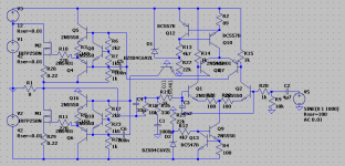
that's probably going to give some nice firework. With R14 connected to GND and no source resistors, biasing is highly dependent on supply voltage. I'd use some kind of current source in the second LTP's tail and also put Q14's collector on GND and the whole front end on some higher supply voltage (around 12-15 V above the outputs) to be able to drive the OPS rail-to-rail for some better efficiency. There should be also some resistance between the driver's emitters to stabilise their Iq. For compensating the OPS' tempco, the controlling transistor (assuming a two transistor CCS) at the 2nd LTP's CCS should be thermally connected to the outputs/heatsink.
I've been thinking to build something like this for some time, here's some schematic (not been built yet) with the suggenstions above applied:
Attachments
Hi EL36
Thank you for your advices 🙂
That's right. Well observed 🙂 I try to build it simple as possible. Maybe I put a simple fet current source in it.With R14 connected to GND and no source resistors, biasing is highly dependent on supply voltage
It's probably better, and its works. At the beginning I had a circuit that ground Q14 and made problems in the simulation. There the dog was buried somewhere else 😉 (german proverb)... put Q14's collector on GND ...
That's also right, but it need a second little power supply.the whole front end on some higher supply voltage (around 12-15 V above the outputs)
The current is so low that I hope there is no need....some resistance between the driver's emitters to stabilise their Iq...
I had already mentioned above 😉For compensating the OPS' tempco, the controlling transistor (assuming a two transistor CCS) at the 2nd LTP's CCS should be thermally connected to the outputs/heatsink.
Thank you for your advices 🙂
The simulations with an additional power source then have convinced me yet.
A bootstrap circuit has also worked, but a small additional transformer makes less effort and works better.
So far, so well...
Here you can see the rail to rail output:
A bootstrap circuit has also worked, but a small additional transformer makes less effort and works better.
So far, so well...
An externally hosted image should be here but it was not working when we last tested it.
Here you can see the rail to rail output:
An externally hosted image should be here but it was not working when we last tested it.
This is the prototype of the board. 100mm x 80mm with 2 x 11mF for power and 1mF for the voltage amplifier.
An externally hosted image should be here but it was not working when we last tested it.
Last edited:
Actually, I do not need a MOSFET with a voltage rating of 200V. My power supply only delivers 2 x 43V anyway. So I looking out of a similar MOSFET. The IRFP4310Z is easier to drive and much cheaper.
Also, I have taken something away from the first differential amplifier gain and thus I get a more stable behavior.
The schematic and the layout have been changed slightly.
Also, I have taken something away from the first differential amplifier gain and thus I get a more stable behavior.
The schematic and the layout have been changed slightly.
The simulations with an additional power source then have convinced me yet.
A bootstrap circuit has also worked, but a small additional transformer makes less effort and works better.
So far, so well...
An externally hosted image should be here but it was not working when we last tested it.
Here you can see the rail to rail output:
An externally hosted image should be here but it was not working when we last tested it.
The topology for Push-Pull driving of each mosfet was also realized by the commercial amplifier brand "GamuT" (design from Mr. Ole Lund Christensen);
check out this threads:
http://www.diyaudio.com/forums/soli...h-pull-pull-like-gamnut-whats-right-name.html
http://www.diyaudio.com/forums/solid-state/66334-gamut-d200-clone.html
What about the sonic character by full-range operation ?
And how much is the perception audible difference between low values and higher values for the idle current through the power mosfet's (e. g. 30-100mA vs. 300-400mA) ?
The design of the circute is not bad, but the Mosfets do not fit. The transconduktance is much to high for analog driving.
It was not possible to find a stabel quiescent current.
It was not possible to find a stabel quiescent current.
- Status
- Not open for further replies.
- Home
- Amplifiers
- Solid State
- Poweramp with IRFP4668