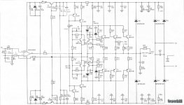
If the bias (with no load) drifts it can only be because the vbe generator is allowing an increase in volts across itself or that it is not correctly positioned to track the output stage temperature changes. Does the voltage across the collectors of T7 and T12 increase as the bias drifts and how does this compare to the good channel.
Thanks for the help, Mooly. Actually, the collectors voltage across T7 and T12 for both channels decrease slowly, only that for the good channel, TS3 and TS4 stabilizes and for the bad channel, the bias voltage increases slowly. Any idea as to why?
Also, how important that the MOSFETS to be matched for this circuit?
Thanks.
Also, how important that the MOSFETS to be matched for this circuit?
Thanks.
yammi yammi .... i was looking for a thing like that long time now !!!!!
first of all what you are talking about is not mosfets !!! BDV xx family is the worst transitor ever used in audio amplifier .....its a darlington and its the king of unstables !!!!
i think what causes your bias drifting is either oscilation or bad thermal design
now .... this the first amplifier ever presented in the forum that has more than one pair of outputs designed arround BDV 65-64 or 66-67 family ( first cousin if not brother of TIP 142 147 ) .... the only one ever presented is the A40 from Nelson pass that features 2pairs per chanel ....
this happilly arises a few very serious questions to be answered ....
1) where the hell did you get BDV 65-64 transitors ? i belive that this impossible to get nowdays ... i could presume that you have BDV 66-67 pairs or TIP 142-147 pairs that are easy to get
2) none of the amplifiers ever presented by many designers ( and that will be only with one pair of outputs) was stable enough to operate with large or very large miller or stabilzation caps and that will be 560 pf from B to C one the outputs ...under this logic the amplifier you have is impossible to operate .Yet again the only exception to this rule will be again the A40 that is biased at 400ma per device ( if memory serves properly ) and that will support my theory that if a darligton is biased high is too bussy to oscilate and becomes actually stable .
3 ) the schematic states 36+36 volt rails ... in this case 3 pairs of outputs to produce 50 Watts is an overkill ( for class AB ) unless your amp is highly biased and closer to class A What is the bias of your amplifier ????
finally ....if transistor are proper ( you may find interesting this thread about what is a proper transitor http://www.diyaudio.com/forums/solid-state/141780-darling-ton-story.html ) then thermals have to be perfectly designed ...pcb have to be perfect ....and bias have to be high ...then yes you might have a chance ...other than that ...i see it as good as a ticking bomb !!!!
experts please join in i enjoy this so much
Thank you for your time
Kind regards sakis
Last edited:
one other thing i missed ...
If you are trying to repair this amplifier and any of the ouputs is blown and you replaced one BDV64 with a BDV 67 or a TIP 147 ( or even much better an NTE replacement )
DUCK NOW !!!! in a few minutes it will be too late !!!!
(I presume that we can share the same sense of humor )
kind regards
Sakis
Last edited:
day time in Athens had a chance to take look a bit more on the schematic and actually i must say that it looks like something i have never seen before
Looked also at the specs of the amp and it looks not really proper clames 120 W@8R and dynamic peaks of 500W( !!!! ) that also means that is class AB bias is low from 36+36 rails ( if schematic is correct ) not realy possible i think
Experts should take a look at it cause the circuit looks interesting and possinly of moded to operate with modern fast transitors might have an option ...of course it will never be a clone of the german thingy but might worth looking at
Possibly a topolgy like that might work better as a PA amplifier taken as a fact that rails are higher and more transitors are in the output than a hifi amp with terrrible outputs ..
Still i belive that someone will have to take a look at this
it is Conrad .... its the same transistor like the outputs ...
yes the double vbe remains an issue
let us not forget that if schematic is correct its a copy of a working design made in Germany and has also documantation and so on and on ...unless some German is messing around with us with a fake schematic
yes the double vbe remains an issue
let us not forget that if schematic is correct its a copy of a working design made in Germany and has also documantation and so on and on ...unless some German is messing around with us with a fake schematic
Last edited:
Maybe I'm missing something. Looks to me like the opamp is directly driving the outputs. I don't see how the opamp with +/-15V to 18V rails can swing the power transistors up to the power rails voltages.
The outputs are (or have the ability to be) fully on via T3 and T5... the opamp and vbe generator is holding them "off" and needs little swing at its output.
- Status
- This old topic is closed. If you want to reopen this topic, contact a moderator using the "Report Post" button.
- Home
- Amplifiers
- Solid State
- Bias Drifting Higher?